Views: 0 Author: Site Editor Publish Time: 2026-11-19 Origin: Site
Did your latest fiber splice fail the OTDR test? Every field technician knows this deep frustration. You meticulously prep the glass. You complete the splice. You expect a flawless connection. Then, the machine reports an unacceptably high dB loss. High loss ruins network performance. It triggers severe signal degradation and wastes valuable hours on costly rework.
Fortunately, these errors rarely happen without a reason. Most attenuation issues boil down to microscopic dirt, a degraded cleaver blade, worn-out electrodes, or an aging machine. In this comprehensive guide, we explore why your equipment underperforms. You will learn step-by-step troubleshooting to fix your current setup, discover field-tested best practices, and figure out exactly when it is time to invest in a reliable fusion splicer.
Cleanliness is Crucial: Over 80% of high loss issues in optical splicing are caused by microscopic dirt in the V-grooves, on the objective lenses, or on the bare fiber itself.
The Cleaver Matters: A poor cleave angle guarantees a high-loss splice, regardless of how advanced your alignment hardware might be.
Routine Maintenance: Regular arc calibration and timely electrode replacement are non-negotiable procedures for maintaining optimal performance.
Hardware Limitations: Chronic high loss often indicates terminal hardware degradation. Upgrading to a modern core-alignment system permanently resolves persistent alignment errors.
Let us look at the current telecommunications landscape. Global networks are pivoting aggressively toward 5G infrastructure and massive Fiber-to-the-Home rollouts. Consequently, optical loss budgets have never been tighter. Modern network architectures leave virtually zero margin for error. We see a clear industry trend where legacy splicing equipment struggles to meet the stringent attenuation standards required by high-density data centers. Understanding the root causes of signal degradation is no longer just a best practice. It is an absolute necessity to prevent costly network bottlenecks.
Before diagnosing a malfunctioning machine, technicians must establish a baseline. Splice loss simply measures the optical power lost at the junction where two optical fibers meet.
Acceptable standards vary depending on network architecture and fiber type. The telecommunications industry broadly adheres to stringent thresholds set by organizations like the TIA and ITU.
For standard installations, the maximum acceptable splice loss is defined as follows:
Fiber Type | Typical Acceptable Splice Loss | Maximum Threshold (Redo Splice) |
|---|---|---|
Single-Mode, SM | < 0.05 dB | > 0.10 dB |
Multi-Mode, MM | < 0.02 dB | > 0.05 dB |
Dispersion-Shifted, DS | < 0.05 dB | > 0.10 dB |
If your device consistently reports losses above these maximum thresholds, you must break and redo the splice. Chronic high readings point to an underlying issue with the equipment, the immediate environment, or your preparation process.
It is critical to understand the difference between estimated loss and actual loss. Modern units use a Profile Alignment System. The device utilizes high-resolution cameras to capture images of the fiber cores on the X and Y axes before and after the plasma arc melts the glass. Algorithms then analyze core alignment and micro-bending to generate an estimated value.
However, this is only an estimate. If objective lenses are clouded by silica dust, the camera miscalculates the alignment. It might provide a false low-loss reading like 0.00 dB while an Optical Time-Domain Reflectometer measures a severe actual loss. Always use an OTDR for objective verification.
Optical fibers have core diameters as small as 9 microns. At this microscopic scale, a single particle of dust acts like a boulder. Statistically, contamination remains the most common reason a splicing machine delivers poor results.
The V-grooves are precision-machined channels cradling the optical fibers during alignment. You might not see dust with the naked eye, but the machine optics certainly do. If silica shards or finger oils accumulate here, the fiber gets pushed upward or sideways.
This physical displacement causes a cladding offset. Even a 1-micron offset between two single-mode fiber cores causes significant optical loss. Remove the fibers and use a stiff, non-linting brush to sweep debris out. Follow up by moistening a lint-free swab with 99% high-purity isopropyl alcohol. Gently run it along the grooves and dry it immediately to prevent solvent residue.
The entire alignment process relies on cameras looking through objective lenses beneath the electrodes. During the fusion cycle, the intense plasma arc vaporizes trace amounts of silica. This eventually settles as a cloudy white residue on the lenses.
When lenses are obscured, the image processor cannot accurately detect the fiber core. The machine forces an improper alignment. To clean them, use a cotton swab lightly dampened with alcohol. Apply a gentle circular sweeping motion from the center outward. Never apply heavy pressure. Scratching the objective lens permanently degrades your machine.
Contamination often bypasses defenses by entering directly via the fiber itself. If the bare glass is not thoroughly cleaned after stripping the acrylic coating, residual debris drags directly into the V-grooves. The fundamental rule of field preparation is simple. Strip, clean, then cleave. Wipe the stripped fiber with an alcohol-soaked wipe until you feel and hear the distinct squeak of perfectly clean glass. Once cleaved, the fiber end must never touch another surface.
A splicing machine only works with the glass it receives. If fiber ends are poorly prepared, the internal computer cannot magically fix them. Specifically, the quality of your cleaver is just as critical as the optical fiber fusion splicer itself.
For a perfect splice, the ends of both fibers must be cleaved at exactly 90 degrees. They must be perfectly perpendicular to the fiber axis. When the plasma arc fires, the glass melts and pushes together symmetrically.
If a cleave angle is poor, the uneven surfaces will not melt evenly. This asymmetry traps microscopic air bubbles inside the joint. It can also cause molten glass to bulge outward and distort the optical path. Light traveling through the core scatters at this distortion. Industry best practice dictates rejecting any cleave angle exceeding 1.0 degree immediately.
Fiber cleavers use a circular tungsten carbide blade to score the glass before tension snaps it. Over time, the sharp edge dulls. A dull blade aggressively crushes the glass instead of scoring it cleanly.
This crushing action results in severe end-face defects like lips, hackles, or micro-cracks. If your device consistently displays error messages regarding end-face quality, rotate the cleaver blade to the next numbered position. Replace the blade entirely before blaming the splicing hardware for the failure.
The splicing process joins glass by generating a high-voltage plasma arc across two tungsten electrodes. The stability, precise temperature, and duration of this arc are absolutely critical.
Electrodes are consumable components. Every time the arc fires, a microscopic amount of tungsten degrades. As they wear down, the tips become blunt or bent. Silica deposits build up as black soot around the metal points.
Worn electrodes produce an erratic or asymmetrical arc. If the arc is too weak, the glass will not melt sufficiently. If asymmetrical, it melts one fiber more than the other. Most manufacturers recommend replacing electrodes every 3,000 to 5,000 splices. Ignoring this schedule guarantees signal attenuation.
Furthermore, environmental factors heavily influence the plasma arc heat intensity. Changes in ambient temperature, barometric pressure, and humidity alter the electrical resistance of the air. A machine calibrated in a warm coastal city applies the wrong amount of heat in a cold mountain environment.
To compensate, technicians must perform an arc calibration test. The unit fires an arc across two cleaved fibers without pushing them together. It measures how far the glass melts back. The software then adjusts the electrical current to achieve the optimal melting temperature. Perform this daily or anytime you move the equipment to a new environment.
Sometimes the hardware functions perfectly, but the physical properties of the optical cables dictate a higher loss.
High loss occurs intrinsically when joining two fibers with different optical geometries. The most common mismatch involves the mode field diameter. This is the actual area where light travels through the fiber core.
If you splice an older ITU-T G.652 single-mode fiber to a newer G.655 non-zero dispersion-shifted fiber, the mode field diameters differ. Light transitioning from the larger core to the smaller core naturally scatters. This intrinsic loss is physics-based. No amount of precise alignment completely eliminates it.
In addition, the alignment method dramatically impacts the final result. Older cladding alignment systems use fixed V-grooves to align the outer diameter of the fibers. They assume the core is perfectly centered. If the fiber has core eccentricity, cladding alignment results in misaligned cores.
In contrast, modern core-alignment systems use precision motors to actively adjust the fibers on the X, Y, and Z axes. They align the actual light-carrying cores perfectly, mitigating eccentricity errors.
At its heart, a splicing machine is a highly sophisticated computer. Operating it with incorrect parameters inevitably yields poor physical results.
These devices contain dozens of pre-configured programs tailored to specific fiber types. Each program dictates a specific arc power, arc duration, and overlap distance.
Multi-mode fibers have a larger core and different melting characteristics than single-mode fibers. If a technician accidentally leaves the machine on a multi-mode program while splicing single-mode fiber, the glass gets under-heated or over-heated. This causes core deformation. Always verify the correct program is active before beginning work.
Manufacturers continually refine image processing algorithms and arc control mechanisms. If a unit runs on outdated firmware, it struggles to recognize newer fiber coatings. Regularly updating the firmware via USB eliminates software-induced bugs and improves camera recognition stability.
Even with meticulous maintenance and frequent arc calibrations, optical equipment has a finite operational lifespan. A machine consistently delivering high-loss readings despite passing all basic troubleshooting steps is likely experiencing hardware degradation. Recognizing these mechanical thresholds is critical for maintaining project efficiency.
The internal architecture relies on highly sensitive components. Over years of deployment in harsh field environments, these components undergo natural wear. Modern systems utilize precision stepper motors. Over thousands of cycles, microscopic gears experience mechanical wear. This introduces physical play into the alignment mechanism. If your device constantly displays motor overrun errors, the drive system is compromised.
Similarly, microscopic dust ingress degrades the protective coatings on objective lenses. Camera sensors develop dead pixels. When power delivery becomes erratic due to aging logic boards, the arc temperature fluctuates. This leads to thermal shock to the glass.
Holding onto a degrading machine feels like a cost-saving measure. However, empirical data suggests hidden operational costs quickly outpace the capital expenditure of a new unit. A technician spending an extra 20 minutes per enclosure troubleshooting high-loss errors accumulates hours of wasted labor each week. Splices that pass internal estimation but fail an OTDR test require rework. This introduces severe project delays and consumes additional splice protection sleeves.
When field diagnostics confirm your current equipment is beyond economical repair, transitioning to modern enterprise-grade technology becomes necessary. Stop looking at basic models and prioritize specifications that directly impact field efficiency.
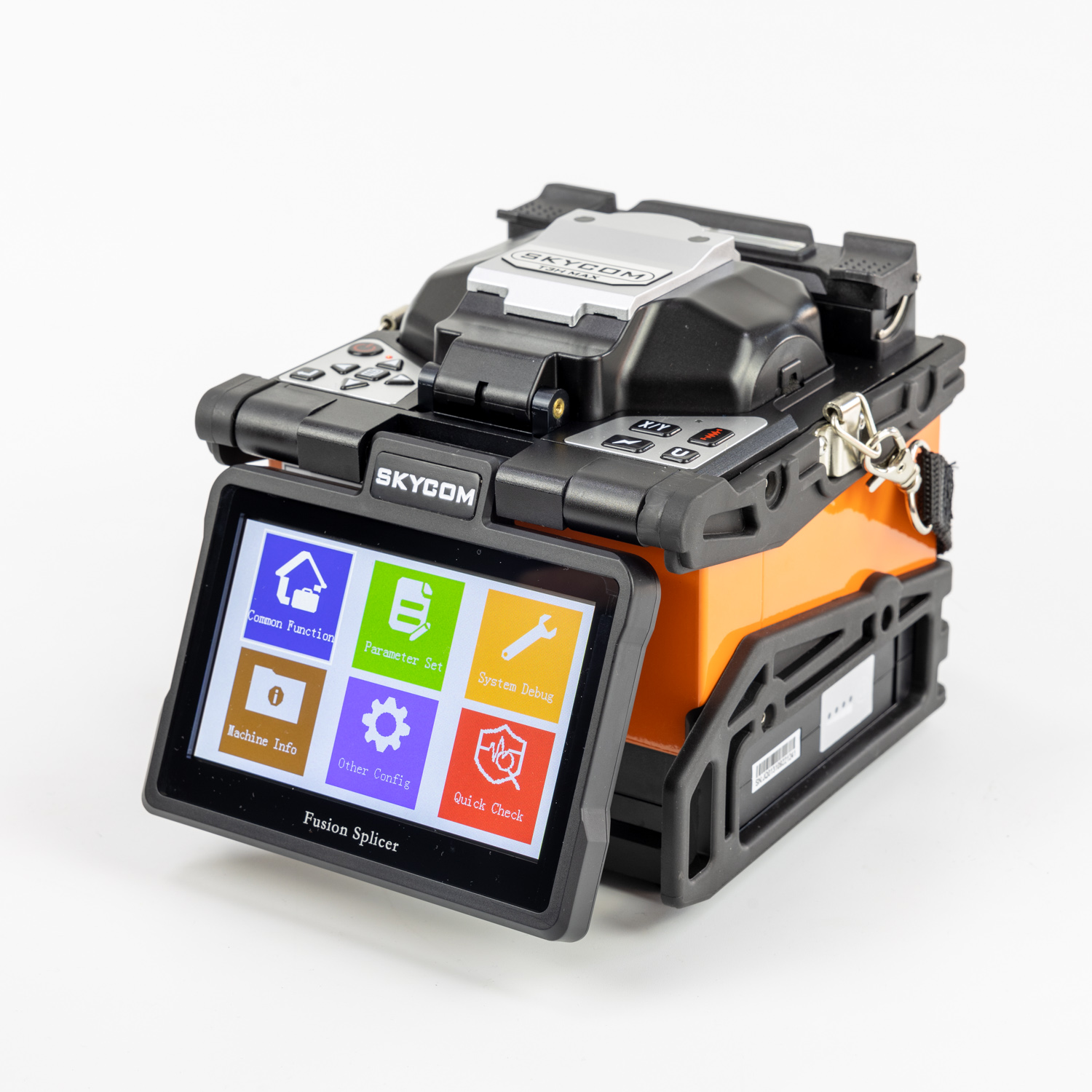
Look for advanced 6-motor core alignment systems. These actively identify the refractive index of the core itself to neutralize concentricity errors. Accelerated processing is also vital. For instance, high-end models like the Skycom T3H fusion splicer optimize thermal heating elements to reduce splice times to an impressive 6 seconds and heating times to under 15 seconds.
Finally, ruggedized environmental protection is non-negotiable. A reliable modern unit must feature an IP52 ingress protection rating to shield delicate optical pathways from wind-blown dust and sudden precipitation. Evaluating a replacement that integrates automated core profiling with robust environmental shielding is your best path forward.
Resolving high-loss splicing issues usually comes down to executing fundamental maintenance. Carefully clean the V-grooves and lenses. Rotate your cleaver blade regularly. Perform arc calibrations when environmental conditions shift. These steps eliminate the vast majority of signal attenuation problems.
A splicing machine is a precision instrument demanding daily care. However, when mechanical wear and aging optics push a machine beyond its useful lifespan, no amount of cleaning saves the splice. If you constantly battle unexplainable errors and failed OTDR tests, it is time to retire your outdated equipment.
Investing in a high-quality solution restores your confidence in the field. It saves countless hours of frustrating rework and keeps your critical infrastructure projects running smoothly. For a seamless upgrade, consider exploring the Skycom T3H to permanently eliminate alignment bottlenecks and boost your daily productivity.
The machine does not physically measure optical light passing through the fiber. Instead, it utilizes a Profile Alignment System to capture high-resolution images of the physical glass joint. It uses a mathematical algorithm to estimate the loss based on core alignment visibility. If there is a microscopic defect within the core that the camera cannot detect, the estimate will be incorrectly optimistic. An OTDR measures the actual backscattered light pulse, revealing the true physical loss of the joint.
Maintenance schedules depend on the operating environment, but industry best practices recommend a strict daily regimen. Inspect and clean the V-grooves, bare fiber pads, and objective lenses with 99% isopropyl alcohol and lint-free swabs at the beginning of every shift. In harsh environments like roadside construction zones, cleaning must be performed multiple times a day.
Absolutely. The splicing machine can only fuse the glass geometry it receives. A high-quality splice requires a perfectly flat end-face with a cleave angle of less than 0.5 degrees. Degraded cleavers produce uneven angles, microscopic lips, or shattered glass edges. When the plasma arc attempts to melt an uneven end-face, the unequal volume of glass causes the joint to bulge, forcing the light to scatter.
Acceptable loss thresholds are defined by international telecommunication standards and specific network engineering budgets. According to general industry guidelines, a successful single-mode fusion splice should exhibit an optical loss of 0.05 dB or lower. Many Tier-1 telecommunications carriers enforce strict contractual limits, requiring splices to be remade if they exceed 0.10 dB.
Fiber breakage during or immediately after the splice cycle usually stems from micro-cracks introduced during the stripping or cleaving process. If your stripping tool is dull or improperly calibrated, it scores the glass cladding. When the machine applies tension during the proof test, the weakened glass snaps. Ensure your stripping tools are sharp and your cleaver blade is at the correct height to prevent structural damage to the bare fiber.
Bubbles trapped inside the fused joint are a classic symptom of poor fiber preparation or incorrect arc parameters. If the fiber end-faces are contaminated with dirt or residual alcohol, the intense heat of the plasma arc vaporizes the impurities, trapping gas pockets inside the molten glass. Additionally, a poor cleave angle or an under-powered arc can prevent the glass from melting uniformly, leaving microscopic air gaps at the core junction.