Views: 0 Author: Site Editor Publish Time: 2026-11-19 Origin: Site
Fiber optic networks serve as the invisible backbone of our modern digital world. They power everything from global financial markets to the streaming video on your smartphone. However, the integrity of these massive communication webs relies entirely on the perfection of microscopic glass connections. A single bad connection can introduce severe latency. Worse, it can completely crash a localized system. Improper splicing inevitably causes high signal loss and critical network failures. Mastering the right techniques ensures decades of uninterrupted data flow.
This is where precision engineering steps in. A fusion splicing machine is a highly specialized instrument designed to weld two optical fibers together using a precisely controlled electric arc. Modern optical equipment is heavily automated. Yet, the machine cannot compensate for poor human preparation. Lack of fundamental understanding during the stripping, cleaning, or cleaving phases will result in fragile connections and costly rework. Field engineers know that a truck roll to fix a single bad splice can cost thousands of dollars in labor and downtime.
Specifically, this comprehensive guide will walk beginners and intermediate technicians through the entire workflow. From staging your workspace and preparing the delicate glass strands to evaluating the final optical weld, you will learn exactly how to achieve a low-loss, professional-grade result every single time.
Cleanliness is an absolute prerequisite: Microscopic dust particles or residual skin oils can instantly compromise an otherwise perfect fiber splice. Meticulous stripping, cleaning with 99 percent isopropyl alcohol, and precision cleaving are non-negotiable steps.
The cleave dictates the splice quality: Advanced machinery cannot correct a jagged or angled cleave. Achieving a flawless 90-degree mirror finish on the fiber end-face remains the most critical preparatory action.
Automation relies on manual accuracy: Once the optical fibers are properly loaded, modern core-alignment machines automatically align the glass cores and apply the exact electrical arc. The initial staging relies entirely on the technician's steady hands.
Post-splice protection is mandatory: Every successful connection must be immediately reinforced with a heat-shrink protective sleeve. This crucial step prevents the highly fragile bare glass from degrading under environmental stress.
Equipment selection drives commercial success: Investing in advanced alignment technology ensures significantly lower optical return loss. This drastically reduces maintenance overhead for long-haul networks and high-speed enterprise data centers.
At its core, a splicing machine is a precision robotic instrument engineered to join two optical fibers end-to-end. The primary objective is to fuse the silica glass together seamlessly. Light pulses passing through the junction must be neither scattered nor reflected back toward the source.
The internal mechanics rely on a combination of microscopic imaging and thermal energy. After the technician prepares and loads the fibers, the machine utilizes specialized high-resolution cameras and stepper motors to align the two microscopic glass strands. Once they are perfectly aligned on the X and Y axes, dual electrodes generate a controlled electrical arc. This intense heat melts the glass ends together, creating a continuous optical path.
Recent industry trends reveal a massive shift in how network operators approach fiber deployment. As the global telecommunications sector aggressively expands 5G infrastructure and high-density fiber-to-the-home architectures, the optical loss budget has become razor-thin. Legacy networks could tolerate minor signal degradation. Today, multi-gigabit symmetrical speeds demand near-perfect physical connections. Industry analysts note that major telecom contractors are entirely phasing out older cladding-alignment tools. Instead, they are standardizing on advanced Advanced Core Alignment Fusion Splicer technologies. These modern units leverage AI-driven image processing to identify and align the exact light-carrying core, compensating for slight manufacturing defects in the glass itself.
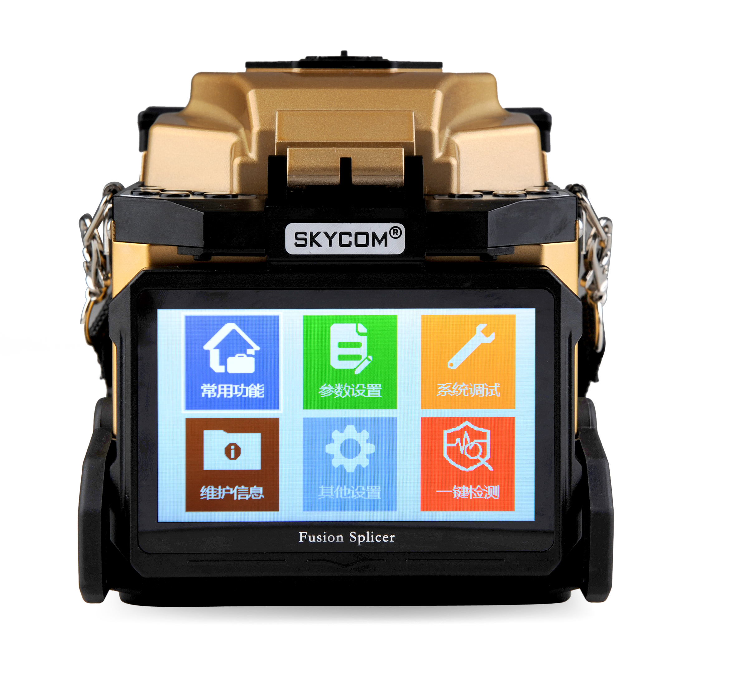
In the telecommunications industry, technicians generally encounter two primary alignment technologies. Cladding alignment focuses on matching the outer 125-micron glass shell of the fiber. It is cost-effective for short-distance networks but lacks absolute precision. In contrast, core alignment utilizes advanced imaging algorithms to look past the outer shell. It aligns the actual light-carrying core, which is a mere 9 microns wide in single-mode fiber. Devices like the SKYCOM T-308X utilize true six-motor core alignment technology. This ensures the lowest possible insertion loss, typically achieving an impressive 0.02 decibel loss for single-mode fibers.
Feature | Core Alignment | Cladding Alignment |
|---|---|---|
Alignment Method | Aligns the inner light-carrying core | Aligns the outer glass shell |
Motor Count | Typically 6 motors for 3D positioning | Typically 2 to 4 motors |
Typical Splice Loss | 0.01 to 0.02 decibels | 0.03 to 0.05 decibels |
Best Application | Long-haul, 5G backbones, Data Centers | FTTH drop cables, short LAN links |
Concentricity Error Handling | Actively compensates for fiber defects | Cannot compensate for core mismatch |
Achieving a low-loss splice requires much more than just the primary welding machine. A complete, well-maintained toolkit is absolutely necessary to prepare, clean, and protect the delicate optical fibers. Attempting to splice without the correct preparatory instruments will inevitably lead to high signal loss, physical breakage, and immense frustration in the field.
This is the primary unit that aligns and welds the optical fibers. A professional-grade machine features a high-definition monitor for visual inspection and a wind protector hood to shield the electrical arc from environmental drafts. It also houses clean tungsten electrodes that deliver the thermal energy. Field engineers look for high magnification displays. For instance, a 300X magnification allows you to see microscopic imperfections before the arc even fires.
A high-precision cleaver is arguably just as important as the splicing machine itself. It is responsible for scoring and breaking the glass to create a perfectly flat end-face. It must achieve a precise 90-degree cut, generally remaining within 0.5 degrees of error. A dull cleaver blade is a technician's worst enemy, leading to endless machine rejections.
Technicians rely on specific hand tools to navigate the tough outer layers of fiber optic cables. A calibrated three-hole fiber stripper is required to remove the outer jacket, buffer, and acrylic coating without scratching the underlying glass. Additionally, Kevlar shears featuring serrated blades are necessary to cut the tough aramid yarn inside the cable. Standard scissors will dull immediately upon contact with Kevlar.
Microscopic debris is the primary enemy of optical integrity. Technicians must use optical-grade, lint-free wipes combined with 99 percent pure isopropyl alcohol. Lower concentrations of alcohol contain water. Water causes micro-boiling when hit by the electrical arc, instantly ruining the splice.
Working with optical fibers inherently involves handling microscopic shards of silica glass. When a fiber is cleaved, the resulting offcut is a tiny, practically invisible splinter. It can easily penetrate the skin or cause severe eye injuries. Therefore, technicians must wear safety glasses and utilize a dedicated disposal container for glass shards. Furthermore, never look directly into a live fiber. The infrared lasers utilized in modern telecommunications are completely invisible to the human eye but possess enough power to cause permanent retinal damage.
Before any stripping or cleaning occurs, you must slide the heat shrink protection sleeve onto one of the fiber ends. This is a deceptively simple yet crucial step. The most common mistake beginners make in the field is executing a flawless splice, only to realize they forgot to load the protective sleeve. Once the fibers are fused into a single strand, you cannot put the sleeve on without intentionally breaking your new connection.
Optical fibers are shielded by multiple protective layers of rugged plastic and soft acrylic. Using a standard three-hole fiber stripper, you must systematically expose the bare glass. First, use the largest hole to remove the outer cable jacket. Next, use the middle hole to strip away the tight buffer coating. Finally, use the smallest hole to gently shave off the acrylic coating, exposing the bare glass cladding. Industry best practices recommend stripping approximately 40 millimeters of fiber to ensure adequate length for cleaning and cleaving.
Once stripped, the exposed bare glass must be meticulously cleaned to remove any remaining acrylic residue. Apply a few drops of 99 percent isopropyl alcohol to a lint-free wipe. Fold the damp wipe over the bare fiber and pull it firmly toward the end. As you pull, you should feel a distinct physical resistance and hear a high-pitched squeak. That sound is your green light. It is the universal field confirmation that all residual debris has been successfully removed. If the fiber glides silently, it is still dirty. You must wipe it again with a fresh section of the cloth.
It is a common misconception that a fiber optic cleaver operates like a pair of scissors. In reality, it does not cut the glass at all. Instead, it operates on the physical principles of scoring and tension. The cleaver utilizes a microscopic tungsten carbide blade to create a tiny scratch on the surface of the glass. The mechanism then applies calibrated mechanical pressure to snap the fiber cleanly along that score line.
This intricate process must yield a perfectly flat, mirror-like end-face at an exact 90-degree angle. If the resulting angle is jagged or sloped, the fusion splicing machine will struggle to align the cores properly. This ultimately results in high optical return loss.
First, open the cleaver lid and carefully place the stripped fiber into the guide channel. You must align the edge of the remaining fiber coating with the appropriate measurement mark on the cleaver pad. Next, close the lid to clamp the fiber securely in place. Slide the blade carriage forward in a smooth, continuous motion to score and snap the fiber. Finally, carefully open the lid and remove the cleaved fiber. Be mindful to safely dispose of the glass offcut.
Once the fiber is successfully cleaved, the bare glass end-face must never touch anything. It must not brush against the workbench, your fingers, or even a fresh alcohol wipe. Any physical contact will instantly contaminate or micro-chip the fragile end-face. The fiber must travel directly from the cleaver into the fusion splicer.
Begin by opening the wind protector hood of the machine and lifting the sheath clamps on both sides of the splicing chamber. Carefully lower the first cleaved fiber into the V-groove. The V-groove is a precision-machined channel designed to physically cradle and guide the fiber. Position the tip of the fiber so it sits exactly halfway between the edge of the V-groove and the tip of the electrode. Gently close the sheath clamp to lock it in place. Repeat this delicate process for the second fiber on the opposite side. Verify that the two fiber ends are in close proximity to each other but are not physically touching.
Modern equipment features intuitive digital menus pre-loaded with calibrated thermal profiles for various fiber types. Navigate the monitor interface to select the appropriate operational mode. Use the single-mode program for long-distance telecommunications. Conversely, select the multi-mode program for short-distance enterprise data centers. Selecting the incorrect program will apply the wrong electrical arc parameters, inevitably boiling or under-heating the glass.
Once you close the wind protector and press the start button, the machine takes over. High-end models execute this sequence incredibly fast. For example, industry-leading core alignment units can complete the entire fusion process in just 8 seconds.
Initially, the machine fires a prefusion arc. This is a brief electrical discharge designed to burn off any microscopic dust particles that settled on the fiber ends during loading. Following this, the alignment phase begins. Internal cameras magnify the fibers on the monitor. Sophisticated stepper motors micro-adjust the strands along the X and Y axes until the light-carrying cores are perfectly aligned.
Next comes the fusion arc. The main electrodes fire, generating intense localized heat that momentarily melts the glass. Simultaneously, the motors push the fibers together, fusing them into a single strand. Finally, the machine conducts a tension test. It applies a slight pulling force to the newly formed splice. This mechanical proof test guarantees the weld is physically robust enough to withstand handling.
Immediately after the tension test concludes, the monitor will display an estimated splice loss measured in decibels. This algorithmic calculation analyzes the alignment geometry and the physical characteristics of the fused glass to predict optical performance.
For single-mode fiber, an estimated loss ranging from 0.01 to 0.02 decibels is considered exceptional. If the screen displays a loss greater than 0.05 decibels, standard operating procedures dictate that the splice is flawed. You should break it and remake it. However, experienced engineers never rely solely on the numerical estimate. Conducting a thorough visual inspection is equally critical.
Analyze the magnified camera views presented on the monitor. A mechanically sound splice should appear as a seamless, continuous piece of glass. Occasionally, you may observe a very faint, perfectly straight vertical line where the fusion occurred. This is normal and acceptable.
In contrast, be on the lookout for visual anomalies. Dark bubbles or thick black lines indicate trapped contaminants or a poor cleave angle. A bulging splice suggests the motors pushed the fibers together too forcefully during the arc. Conversely, a noticeable thinning of the glass indicates that the electrical arc was too hot. If your equipment consistently produces poor splices despite flawless preparation, troubleshooting is required. Common culprits include a degraded cleaver blade or debris trapped in the V-grooves.
A successful fusion splice creates a continuous optical path. However, the bare glass at the fusion point remains incredibly fragile. Stripping the protective acrylic coating exposes the silica cladding, which is roughly the thickness of a human hair. Without immediate reinforcement, the slightest bending force will snap the glass. Consequently, applying a heat shrink splice protector is a mandatory step.
First, open the wind protector and gently lift both sheath clamps simultaneously. Lift the newly spliced fiber straight up. Keep the fiber taut with both hands to avoid bending the splice point. Next, carefully slide the pre-staged heat shrink protection sleeve over the exposed glass. Ensure that the rigid steel strength member inside the sleeve spans entirely across the bare glass and overlaps the acrylic coatings on both sides. An off-center sleeve creates a dangerous hinge point that will eventually cause a fiber break.
Once perfectly positioned, place the assembly into the built-in tube heater and press the heat button. Premium machines feature rapid heating capabilities, shrinking the sleeve in as little as 15 seconds. The heater activates a specific thermal profile. It shrinks the inner adhesive tube to encapsulate the glass, followed by the outer polyolefin tube to secure the assembly into a rigid block. Remove the hot sleeve and place it on a designated cooling tray for a few minutes before transferring the fiber to a splice tray.
The overall success of your fiber optic deployment relies heavily on matching your equipment to the specific demands of your project. Different networking environments require vastly different technical specifications. Buying the wrong machine leads to either massive optical failures or wasted capital expenditure.
If your team handles temporary repairs or FTTH drop cables in residential areas, a basic cladding-alignment machine might suffice. Shorter distances generally allow for higher loss tolerances. The initial investment is lower, making it suitable for basic contracting work.
However, if you are building long-haul backbone networks, 5G cellular towers, or high-speed enterprise data centers, you demand absolute precision. In these unforgiving environments, accumulated signal loss across multiple splice points causes severe latency or catastrophic downtime. For professionals seeking reliable performance in these demanding sectors, investing in the SKYCOM T-308X fusion splicer is highly recommended. Featuring six-motor core alignment, a 5200mAh high-capacity battery for continuous field operations, and an ultra-fast 8-second splice time, it actively compensates for fiber concentricity errors. This ensures the lowest possible insertion loss on the very first attempt.
When evaluating professional-grade machinery, prioritize features that enhance field efficiency. Look for ruggedized casing for robust protection against dust and water. Selecting the right tool guarantees long-term network integrity. It also significantly reduces the exorbitant labor costs associated with troubleshooting failed connections.
Fiber optic splicing is a meticulous process that perfectly blends scientific precision with practiced manual dexterity. Mastering the preparation phase is the foundation of success. Maintaining absolute cleanliness and executing perfect cleaves will prevent the vast majority of signal loss issues. While modern equipment brilliantly automates the complex welding process, the technician's careful handling ensures the connection survives in the real world.
For beginners, developing the muscle memory required for stripping and cleaving takes time and patience. Consistent practice yields rapid improvement. Always remember to perform routine daily maintenance on your equipment to ensure reliable results. Take the time to audit your toolkit before your next deployment. Upgrade your machinery if your network demands higher precision, and approach every splice with the care it requires to keep our digital world connected.
Core alignment uses advanced cameras and six internal motors to look through the outer glass shell and align the microscopic light-carrying core directly. This method compensates for manufacturing defects in the glass, resulting in ultra-low splice loss ideal for long-distance and high-speed networks. Cladding alignment only aligns the outer physical shell of the fiber using fewer motors. It assumes the core is perfectly centered, which makes it cheaper but less precise, suiting it only for short-distance applications.
Splices breaking during or immediately after the heat-shrink process usually point to micro-fractures introduced during preparation. If you nick the bare glass with your fiber strippers, the structural integrity is compromised, and the tension of the shrinking sleeve will snap it. Another common cause is bending the fiber while transferring it from the V-grooves to the heating oven. Always keep the fiber perfectly taut and straight during this transfer.
The total time required depends heavily on the technician's experience. Stripping, cleaning, and cleaving the fiber typically takes an experienced technician about one to two minutes. Once loaded, a high-end machine completes the automated alignment and fusion process in just 8 seconds. Curing the heat shrink protection sleeve requires about 15 seconds. In total, a single splice can be completed and securely protected in under three minutes.
High-end machines possess the physical capability to weld single-mode glass to multi-mode glass. However, doing so is highly discouraged in practical networking environments. Single-mode fiber features a tiny core diameter of 9 microns, whereas multi-mode fiber has a much larger core diameter of 50 or 62.5 microns. Fusing these mismatched cores creates a severe optical bottleneck. Attempting to transmit light from a 50-micron core into a 9-micron core results in massive insertion loss and immediate transmission failures.
If the machine halts the automated process and displays an error before the electrical arc fires, it has detected a physical anomaly. The most frequent cause is a poor cleave angle. If the end-face angle exceeds 1.0 degree, the safety protocols will reject it. Other culprits include microscopic dust on the objective lenses, debris inside the V-grooves, or failing to push the fiber ends close enough to the electrodes during loading.
Electrodes are consumable components that naturally degrade over time due to extreme heat. During fusion, microscopic amounts of silica vaporize from the glass and deposit onto the tungsten tips. This buildup causes the arc to become unstable. Most standard electrodes are rated for 3,000 to 5,000 arc discharges. Modern machines actively track the arc count and prompt you with a maintenance warning. Always run an arc calibration sequence immediately after installing new electrodes.
Ready to eliminate costly rework and drastically improve your network reliability? Stop fighting with outdated equipment that struggles to meet modern optical loss budgets. Explore our industry-leading fusion splicer solutions today and equip your field teams with the precision tools they need to build the networks of tomorrow.