
Views: 0 Author: Site Editor Publish Time: 2026-09-24 Origin: Site


Working in a cramped splice closure in the freezing rain? Or maybe you are building a massive high-speed backbone. Either way, the quality of your entire network relies on one microscopic moment. That moment is the cleave. A single bad cut can introduce enough reflectance to ruin an entire gigabit network.
Novice technicians often assume that joining two fiber optic cables is just a matter of lining them up and melting them together. This is a costly misconception. Doing the preparation tasks out of order inevitably causes massive signal loss. It wastes valuable silica glass. It also causes severe damage to expensive fusion equipment. In this comprehensive guide, you will learn the exact step-by-step process to prepare your cables. We will demonstrate the strictly enforced sequence required to cut fibers safely and effectively. This ensures a flawless connection every single time.
Key Takeaways
The absolute correct sequence for fiber preparation is always: Strip, Clean, Cleave. You must never alter this mechanical order under any circumstances.
Wiping the bare glass with alcohol before using your cutting tool prevents microscopic blade damage. It ensures a mathematically precise, flat cut.
A high-precision desktop tool is non-negotiable. You need it to achieve the strict sub-1-degree angle required for modern fusion splicing.
Proper disposal of microscopic glass shards is a critical safety protocol. Field workers must never ignore this hazard.
To fully grasp why the sequence of operations matters so much, technicians must first understand the fundamental mechanics of glass preparation. Global broadband deployment is shifting rapidly toward ultra-low-loss 5G networks and high-density FTTH architectures. In these modern environments, optical loss budgets are tighter than ever. A decade ago, a marginal splice might have passed certification. Today, that same splice will fail a bidirectional OTDR test instantly. This strict industry standard means field technicians can no longer rely on guesswork.
The term is frequently misunderstood as simply cutting the fiber. In reality, silica glass cannot be sliced like a standard copper electrical wire. Never use heavy-duty scissors or standard wire cutters on a fiber optic cable. The delicate core will instantly crush. It shatters and splinters uncontrollably inside the protective jacket.
Cleaving is actually a strictly controlled process of applying mechanical stress to the material. A specialized, ultra-sharp blade makes a microscopic score on the outer surface of the 125-micron glass cladding. Think of it as a tiny, precise scratch. Immediately after this score is made, the tool applies controlled tension or downward bending force to the strand. This specific force causes the microscopic scratch to propagate across the entire diameter of the glass at the speed of sound. The result is a perfectly clean, flat break.
Optical networks transmit vast amounts of data using rapid light pulses. For these pulses to pass from one cable to another successfully during a splice, the two glass end-faces must align with microscopic perfection.
Poor preparation will result in an angled cut. When two slanted cuts are pushed together in a splicer, microscopic air gaps and physical misalignments occur. Consequently, this leads to two severe network degradation issues. First, insertion loss occurs when light escapes from the core at the splice point. This permanently weakens the signal. Second, reflectance happens when light bounces off the uneven glass surface and travels backward. This backward reflection can severely damage sensitive laser transmitters at the source.
Before executing any physical cuts, a technician must properly prepare their workstation. Attempting to prepare a fiber without the proper supporting equipment will inevitably lead to core contamination or mechanical failure.
Professional field preparation requires a highly specific set of tools. Substituting these items with household alternatives will permanently compromise the integrity of the glass.
Fiber Optic Strippers: Required to remove outer jackets and protective buffer coatings. They must have precise, factory-calibrated holes to avoid nicking the underlying glass.
Lint-Free Wipes: Used to wipe away dissolved coating residue and natural oils. Standard paper towels are unacceptable. They leave microscopic debris behind.
Isopropyl Alcohol: Must be 99% pure to dissolve the acrylate coating residue effectively. Standard 70% rubbing alcohol contains water. Water causes disastrous micro-boiling inside fusion splicers.
The market offers various types of cutting devices. These are primarily divided into cheap pen-style tools and precision desktop units. Pen-style models require the user to manually score and snap the fiber by hand. This subjective, manual process rarely produces the sub-1-degree angles required for modern networks.
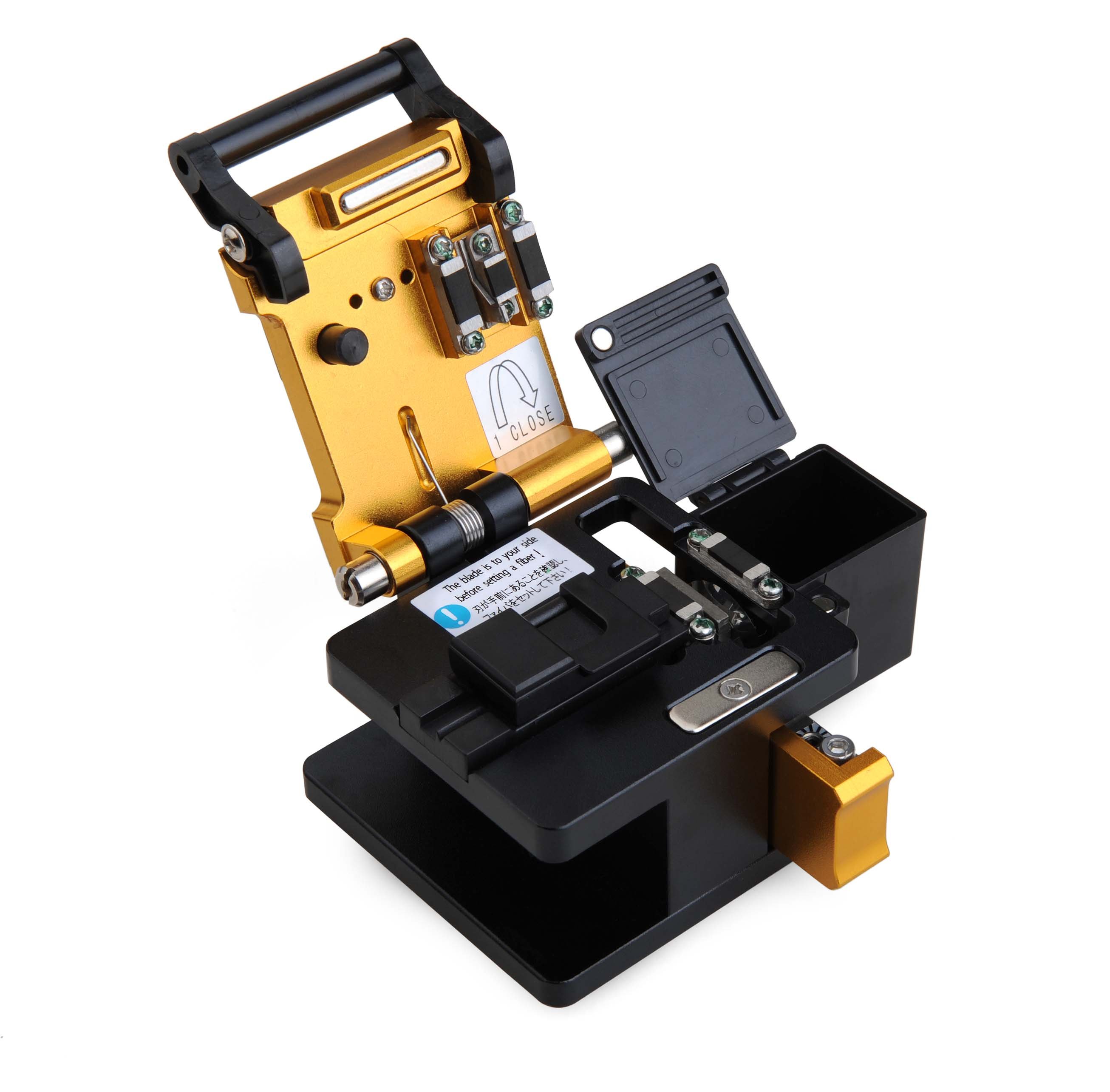
For professional installations, investing in a dedicated high-precision optical fiber cleaver is an absolute necessity. These desktop tools automate the scoring depth and snapping tension. They entirely remove human error from the equation. Utilizing a professional-grade unit directly correlates to lower splice failure rates and significantly reduced labor costs in the field.
The absolute correct order of tasks begins with stripping. You cannot chemically clean or mechanically score a fiber that is still encased in its thick protective polymer layers. This is the crucial first step.
A standard single-mode strand consists of a microscopic 9-micron core surrounded by a 125-micron glass cladding. This incredibly delicate structure is protected by a 250-micron acrylate coating. It is also often covered by a thicker 900-micron tight buffer.
To strip the cable, the technician uses specialized stripping pliers. Hold the tool at a slight 45-degree angle. Place the cable into the appropriate sizing hole and firmly pull the tool toward the end of the strand. This action shaves off the plastic and polymer layers, exposing the bare silica. Typically, you need to strip about 30 to 40 millimeters. This ensures you have enough bare glass to sit properly in your equipment.
Once the 125-micron glass is exposed, it is incredibly fragile. It is thinner than a human hair and prone to snapping under the slightest lateral pressure. Imagine standing in a muddy construction trench. Your hands must remain perfectly steady. Technicians must hold the cable by the remaining jacketed section. Never hold it by the bare glass itself. Touching the exposed silica with your bare fingers will deposit natural skin oils. This immediately contaminates the core and guarantees a splice failure.
Following the stripping phase, the second task in the sequence is chemical cleaning. You must never skip this step. This is precisely where many novice technicians make critical, expensive errors. They attempt to cut the glass before washing it.
When the acrylate coating is forcefully stripped away, it leaves behind an invisible, sticky residue on the bare glass. To remove this stubborn layer, take a lint-free wipe and moisten it generously with 99% isopropyl alcohol. Fold the wipe over the bare strand. Pinch it gently between your fingers, and pull the wipe smoothly toward the end of the glass.
During this motion, technicians should listen closely for a distinct squeak sound. This high-pitched auditory feedback is your confirmation that all polymer residue and oils have been successfully dissolved. You may need to wipe the strand two or three times to achieve this perfectly clean state.
The golden rule of cleaning before you cleave exists primarily to protect your expensive hardware. If you place an uncleaned, sticky strand into a desktop optical fiber cleaver, the microscopic residue will immediately transfer onto the tool. It coats the rubber clamping pads and the ultra-hard tungsten carbide blade.
Over time, this invisible dirt builds up. When the blade attempts to score the glass, the hardened dirt acts like a microscopic boulder. It causes the blade to violently chip the glass rather than score it smoothly. Furthermore, if you make the mistake of cleaning the glass after it has been cut, the physical friction of the wipe will attract airborne static dust. This dust lands directly on the freshly cut, perfectly flat end-face. It completely ruins the mirror finish you just created.
With the strand properly stripped and chemically cleaned, you are now ready for the third and final physical preparation task. The mechanical operation of a standard desktop unit follows a strict internal sequence to guarantee success.
First, ensure your tool is resting on a flat, highly stable surface. Open the main top lever of the unit. Inside, you will see a precision-machined V-groove and two rubber clamping pads. Gently lay the cleaned, bare glass into the V-groove. It is absolutely critical that the strand sits perfectly straight. Any bowing or bending will result in a disastrously slanted end-face.
Fusion splicers require a very specific length of bare glass to operate correctly. This is known as the cleave length. Look at the built-in ruler adjacent to the V-groove. Depending on your splicer specifications, align the edge of the outer jacket to the correct millimeter mark. Standard lengths range from 10 millimeters to 16 millimeters. Accurate alignment ensures the strand will sit perfectly between the fusion splicer electrodes later.
Once the alignment is verified, close the top cover. This action lowers the rubber pads. It firmly clamps the strand in place so it cannot shift. Next, actuate the blade mechanism. On most modern desktop units, this involves pushing a sliding carriage from the front of the tool to the back. As the carriage glides forward, the circular tungsten blade gently grazes the underside of the clamped glass. This creates a mathematically precise scratch on the cladding.
Immediately after the blade scores the surface, the tool internal mechanism presses a small anvil down onto the glass. This occurs directly above the score line. It applies the exact amount of mechanical tension required to snap the strand cleanly.
The offcut is the tiny piece of glass that breaks away. This shard is extremely dangerous. It is sharp enough to easily penetrate skin, travel through the bloodstream, or cause severe ocular damage. High-quality professional units feature automatic shard catchers. These instantly grab the severed glass and store it safely. If your tool lacks this feature, you must manually pick up the offcut with tweezers. Always place it in a dedicated sharps disposal bin.
The preparation process is not truly complete until the quality of the cut has been empirically verified. The naked human eye cannot possibly determine if a strand has been cut at an acceptable 0.5 degrees or an unacceptable 3.0 degrees.
To inspect your work, carefully transfer the prepared strand into your fusion splicer. Once both sides are loaded, the machine will utilize high-definition microscopic cameras on the X and Y axes. It displays the end-faces on its LCD screen. The internal software will instantly analyze the geometry of the cut and calculate the exact angle. For standard single-mode splicing, the machine will typically reject any cut with an angle greater than 1.0 degree.
If the splicer rejects the strand, you must be able to identify the visual defect on the screen. This allows you to troubleshoot your workflow.
Lip: A small protrusion or spike on one edge of the glass. This is usually caused by an incorrect blade height.
Hackle: A rough, jagged, and uneven surface across the end-face. This is often the result of too much tension during the snap or dirt on the rubber pads.
Chip: A missing chunk of glass at the edge of the cladding. This indicates the blade is chipped or hitting the glass too aggressively.
High Angle: The end-face is smooth but visibly slanted. This means the strand was placed diagonally in the V-groove.
If you encounter any of these defects, you cannot simply re-cut the same piece of bare glass. You must cut off the exposed section, strip a new section of jacket, clean it thoroughly again, and repeat the entire sequence.
Even when technicians fully understand the correct sequence, mechanical execution errors during the final step can still compromise the entire connection. Silica glass is incredibly unforgiving. Avoiding common workflow errors is just as critical as following the steps. To highlight the impact of these errors, review the core comparison table below.
Preparation Phase |
Correct Standard Procedure |
Common Field Error |
Network Consequence |
|---|---|---|---|
Stripping |
Use factory-calibrated stripping pliers |
Using dull or incorrect gauge tools |
Micro-nicks on the glass cladding causing future breaks |
Cleaning |
Wipe with 99% IPA before scoring |
Wiping the glass after cutting |
Burnt carbon spots during fusion arc, massive signal loss |
Cleaving |
Use a precision desktop tool |
Hand-snapping or using pen-style cutters |
High reflectance, jagged hackles, and angled cuts > 1.0° |
This table clearly illustrates why cleaning the fiber after cleaving is so detrimental. Wiping a cut strand with a wipe will leave microscopic fibers or static dust directly on the core. When the fusion splicer attempts to melt the glass with an electrical arc, this dust will instantly burn. It creates a black carbon spot inside the joint. This guarantees massive insertion loss and a completely failed connection.
Understanding the strict requirements of network preparation highlights exactly why tool selection is a critical business decision. Utilizing subpar equipment introduces unpredictable variables into network deployment. It leads to failed splices, network downtime, and incredibly expensive truck rolls for troubleshooting.
For technicians seeking reliable, repeatable performance that aligns with modern network demands, investing in a professional SKYCOM T-903 optical fiber cleaver represents a standardized solution. It is designed specifically for high-volume environments.
Instead of relying on abstract marketing claims, experienced engineers look at hard specifications. The SKYCOM T-903 is engineered with a high-precision tungsten steel blade capable of delivering a typical cleave angle of less than 0.5 degrees. This easily meets the strictest fusion splicing requirements. Furthermore, it features a robust 16-position blade design. This provides an exceptional lifespan of up to 48,000 cleaves before requiring a blade replacement.
Specifically, tools in this elite class feature a 3-in-1 universal fiber holder. This allows technicians to seamlessly transition between 250-micron bare fiber, 900-micron pigtails, and 3.0-millimeter drop cables without swapping fixtures. By integrating a reliable tool with automatic blade return into your daily workflow, technicians can maintain strict adherence to the Strip, Clean, Cleave methodology. This drastically minimizes field defects.
Proper fiber preparation requires unwavering adherence to a very specific sequence. You must strip the jacket, clean the bare glass, and finally, cleave the strand. This exact order is the only way to prevent severe equipment damage. It ensures ultra-low signal loss across your network.
Always remember to chemically clean the bare silica before you score and snap it. Attempting to reverse these steps will only introduce static dust to your pristine end-face. Ultimately, pairing this strict procedural knowledge with a professional optical fiber cleaver will significantly improve your installation quality. It reduces frustrating rework and helps you achieve perfect splices every single time. If you are struggling with inconsistent splice results, it is time to upgrade your preparation tools to match the demands of modern optical networks.
An incorrect cut fundamentally compromises the physical geometry of the glass. When the end-face is jagged, chipped, or angled greater than 1 degree, the two ends cannot align perfectly inside the fusion splicer. This misalignment leads to high insertion loss and high optical return loss. In modern high-speed networks, these reflections cause severe data packet loss and can completely crash the connection.
Most precision tungsten steel blades feature 16 to 24 specific rotational positions marked on the side of the wheel. As a general industry guideline, you should rotate the blade one position forward after approximately 1,000 to 3,000 cuts. However, the true indicator is visual feedback from your fusion splicer monitor. If you begin to notice a consistent increase in bad angles or visually chipped end-faces on the screen, you must rotate the blade immediately.
Absolutely not. Scissors and wire cutters operate by applying crushing force. Because the core and cladding of an optical cable are made of highly fragile silica glass, crushing force will completely shatter the microscopic structure. This destroys the light-guiding pathways. A dedicated precision device does not actually cut the material. It uses a microscopic blade to create a tiny flaw, then applies precise tension to cleanly snap the glass along its natural crystalline structure.
Always clean the glass BEFORE you cut it. This is the golden, unbreakable rule of preparation. Once the cable has been stripped of its protective coating, it must be wiped with 99% isopropyl alcohol until it squeaks. This removes all dirt and buffer residue, protecting the delicate internal blade from contamination. If you clean the glass after it has been cut, the static electricity generated by the wiping motion will attract microscopic lint directly onto the core.
A high angle error usually means the glass was not sitting perfectly straight in the V-groove during preparation. This happens when microscopic dust or sticky acrylate residue builds up in the groove, elevating one side of the strand. Always clean your V-groove and rubber clamping pads with an alcohol swab before starting your shift.
No. If your splicer rejects a cut, you do not have enough bare glass remaining to simply place it back into the cutting tool for a second try. You must cut off the exposed section entirely. Then, you strip a fresh section of the outer jacket, clean it thoroughly with alcohol, and perform a brand new cut.


