Views: 0 Author: Site Editor Publish Time: 2026-08-12 Origin: Site
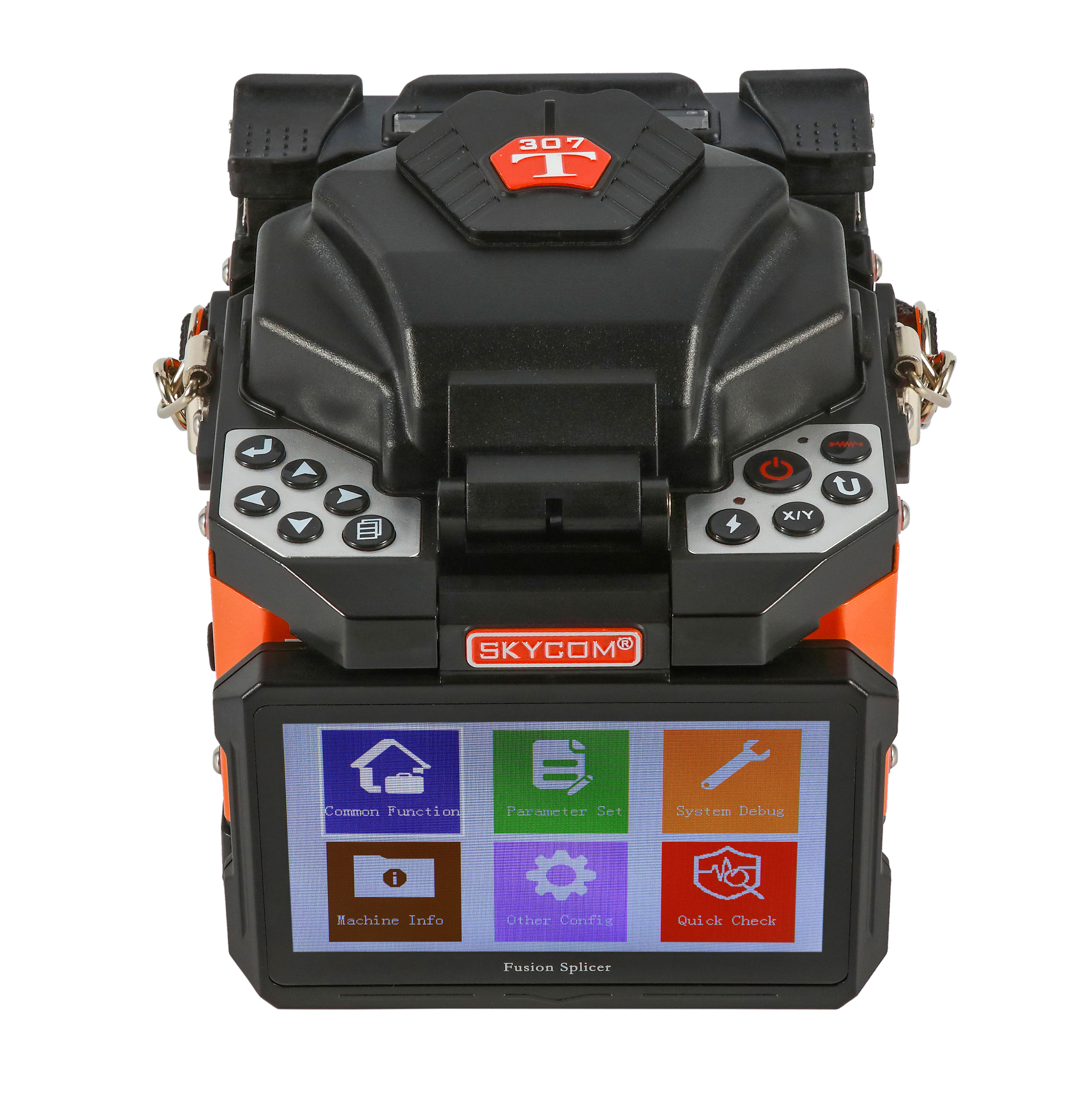
Signal attenuation remains a fundamental challenge in modern optical network deployment. Every connection point introduces potential signal degradation. A high-quality splice makes the difference between a highly resilient network and costly, recurring truck rolls. Technicians rely on a Fiber Fusion Splicer to solve this exact problem. This specialized precision equipment automatically aligns and welds two optical fibers together using a controlled electric arc. The resulting permanent joint ensures near-zero light reflection and absolute minimal insertion loss, maintaining optical signal integrity across vast distances. However, navigating the current market of splicing equipment can feel overwhelming. Choosing the right splicer requires carefully balancing your deployment scale against required splice loss thresholds and harsh environmental conditions. In this guide, you will learn how modern splicing technology works, how to choose between core and cladding alignment, and the essential maintenance routines needed to guarantee reliable network rollouts.
A fiber fusion splicer automates the alignment and melting of two optical fibers, consistently achieving insertion losses below 0.02dB.
Procurement decisions hinge on alignment technology: core alignment is mandatory for long-haul and legacy fiber, while active cladding alignment suits many FTTH applications.
A dedicated FTTH fusion splicer prioritizes portability, battery life, and compatibility with drop cables over absolute lowest-loss metrics.
Total cost of ownership extends beyond the splicer itself; high-precision cleavers and regular electrode maintenance are non-negotiable for consistent performance.
Creating a permanent, low-loss connection between two microscopic glass fibers requires incredible precision. You cannot simply glue them together. You must melt and fuse them into a single, continuous strand. The modern splicing machine handles this through a highly automated, carefully calibrated process.
Once you strip, clean, and properly cleave the fibers, you place them into the machine. The equipment then takes over to execute a strict sequence of events. This sequence guarantees optimal alignment before any permanent melting occurs.
Fiber Feeding: Precision motors move the two fiber ends toward the center of the splicing chamber.
Pre-Fusion Arc: The electrodes fire a brief, low-intensity electrical arc. This step burns off residual microscopic dust or moisture.
Optical Alignment: Internal cameras inspect the fiber ends. They calculate the necessary adjustments to align the cores perfectly.
Main Fusion Arc: The machine delivers a controlled, high-intensity electrical discharge. This melts the silica glass precisely at the junction point.
Splicing and Forging: The motors gently push the molten fiber ends together to form a seamless joint.
Cooling and Inspection: The cameras inspect the newly formed joint for bubbles or visible defects.
Tension Test: The machine applies a brief mechanical pull. This confirms the physical strength of the new splice.
The core principle behind this equipment is controlled thermal dynamics. The electrical discharge melts the silica glass without destroying its internal structure. It requires precise temperature management. If the arc burns too hot, it distorts the glass. This alters the refractive index of the fiber core and causes severe light leakage. If the arc burns too cold, the glass fails to bond completely. Proper machines monitor environmental variables like temperature and air pressure. They adjust the arc power dynamically to maintain the exact melting point of silica glass.
After completing the splice, the machine displays an estimated loss value on the screen. Novice technicians often mistake this for a definitive measurement. It is not. The machine calculates this number based on camera alignment data and geometric algorithms. It evaluates how well the cores lined up visually. However, this visual estimation does not pass actual light through the cable. To validate the true insertion loss of your connection, you must perform testing with an Optical Time-Domain Reflectometer (OTDR). The OTDR remains the industry standard for verifying network integrity.
When you evaluate splicing equipment, alignment technology serves as the primary differentiator. This single feature dictates the machine's complexity, physical size, and appropriate use cases. You must choose the right alignment method for your specific network architecture.
These sophisticated machines look directly at the actual core of the fiber. They utilize multiple high-resolution cameras and advanced motor systems across three spatial axes (X, Y, and Z). The equipment literally peers through the outer glass layers to locate the microscopic light-carrying center.
Sometimes, manufacturing flaws cause the core to sit slightly off-center within the cladding. Core alignment machines compensate for these concentricity errors automatically. They physically manipulate the fibers until the cores align perfectly. You need this technology for long-haul networks, heavily aged fiber deployments, and critical trunk lines. In these environments, you must aggressively minimize cumulative signal loss across vast distances.
Instead of looking at the internal core, these machines align the outer surface of the glass. They rest the fibers in precise V-grooves. Moving motors then adjust the fibers along the X and Y axes to align the outer cladding layers.
This technology operates on a simple assumption: if the outer surfaces align, the inner cores should also align. This holds true for modern, high-quality single-mode fibers with excellent factory concentricity. Active cladding alignment suits short-haul networks, enterprise LAN environments, and standard middle-mile distribution. The equipment weighs less, processes splices faster, and requires less complex optics.
Procurement teams must weigh upfront capital requirements against acceptable loss budgets. If your network design permits an average splice loss of 0.03dB, cladding alignment provides excellent efficiency. If your long-haul architecture strictly demands average losses below 0.01dB, you must deploy core alignment models.
Splicing Technology Comparison Chart
Feature | Core Alignment | Active Cladding Alignment |
|---|---|---|
Alignment Focus | Inner light-carrying core | Outer glass surface |
Camera & Motor System | Highly complex (6+ motors) | Moderate complexity (4 motors) |
Typical Splice Loss | 0.01dB to 0.02dB | 0.02dB to 0.04dB |
Best Use Case | Long-haul, legacy fiber trunks | FTTx, LAN, short-haul |
Fiber-to-the-Home (FTTH) deployments introduce entirely different challenges compared to traditional trunk line construction. Technicians no longer work in controlled environments or spacious splicing trailers. They navigate tight crawl spaces, bucket trucks, and unpredictable weather. This reality demands a specialized tool.
When working on last-mile drop points, massive core-alignment machines become cumbersome. A dedicated FTTH Fusion Splicer provides a much smaller, handheld form factor. Engineers design these units for maximum agility. Technicians can wear them on a harness, operate them on a small utility tray, or mount them directly to a ladder. This compact design reduces technician fatigue and accelerates installation times in dense residential neighborhoods.
FTTx workflows require handling diverse cable types. A standard trunk machine typically focuses on bare 250µm or 900µm fibers. However, a specialized last-mile machine must adapt to various consumer-facing cables. Key compatibility features include:
Universal Fiber Holders: Capable of securing 250µm, 900µm, 2mm, and 3mm jackets without requiring manual holder swaps.
Drop Cable Support: Specifically engineered clamps to hold flat indoor/outdoor drop cables securely during the splicing process.
Splice-On Connector (SOC) Compatibility: Custom heating ovens designed to cure SOCs quickly, allowing technicians to terminate directly at the customer premises.
Engineering a machine specifically for FTTH requires a deliberate compromise. Last-mile deployments do not span hundreds of kilometers. Therefore, they do not require the absolute microscopic precision of core alignment. Instead, an FTTH machine optimizes for rapid heating cycles and extended battery life. A technician might perform 50 to 100 splices per day across multiple houses. Shaving 10 seconds off each heating cycle yields massive labor efficiency gains. The machine prioritizes high-volume daily output over chasing a 0.01dB loss threshold.
Purchasing the right equipment dictates the speed and reliability of your entire network rollout. You must look beyond simple marketing claims and evaluate machines based on harsh field realities. A unit that performs well in a laboratory might fail miserably in a humid, dusty trench.
Field equipment takes serious abuse. You should look for machines carrying an IP52 rating or higher. This standard guarantees protection against fine dust ingress and falling water drops. Wind resistance also plays a critical role. The machine must maintain a stable arc even when exposed to heavy wind gusts. Furthermore, review the manufacturer's drop-test compliance. A sturdy rubberized casing often prevents catastrophic camera misalignment if a technician drops the unit from a utility tray.
Never evaluate a machine based on splice time alone. The actual bottleneck always lies in the heat shrink oven. Many machines execute a splice in 6 seconds but take 30 seconds to shrink the protective sleeve. You must calculate labor efficiency based on the combined splice-plus-heat cycle time. Modern high-efficiency models can finish the entire sequence in under 15 seconds. In mass deployments, saving 20 seconds per joint compounds significantly across a large workforce.
Power availability dictates field productivity. Assess the total number of splice-and-heat cycles a single battery charge provides. A standard machine should deliver at least 200 cycles per charge. High-capacity models can push beyond 300 cycles. Additionally, evaluate the design of the battery itself. Hot-swappable batteries allow technicians to insert a fresh power cell without powering down the machine. This eliminates reboot delays and keeps the workflow continuous.
Managing dozens of machines across multiple contracting crews requires oversight. Modern units feature Bluetooth or cloud connectivity. These tools log every single splice, recording the estimated loss, environmental data, and timestamp. Fleet managers can track compliance remotely. If a machine falls out of calibration or gets stolen, administrators can lock it out via remote firmware updates. This data-driven approach ensures quality control across decentralized teams.
Buying premium splicing equipment does not automatically guarantee low-loss connections. The machine represents just one part of a broader ecosystem. Field success heavily relies on auxiliary tools and strict daily maintenance routines. Ignoring these realities leads to high failure rates and frustrated technicians.
A splicing machine is only as good as the cleaver feeding it. You cannot weld broken, jagged glass effectively. The cleaver scores and snaps the fiber to create a perfectly flat 90-degree end face. If the cleaver blade dulls or the anvil misaligns, it creates a bad cleave angle (greater than 0.5 degrees). When you feed a poorly cleaved fiber into the machine, it guarantees a high-loss splice. The machine will either reject the fiber entirely or attempt to melt the uneven glass, creating a distorted joint. You must invest in high-precision cleavers and rotate their blades religiously.
The electrodes act as the spark plugs of your machine. Every time they fire an arc, microscopic amounts of tungsten burn away. Over time, this wear and tear alters the shape of the electrical discharge. Typical electrodes last between 3,000 and 5,000 arcs. Once they degrade, the machine loses its ability to maintain stable arc temperatures. You must establish strict field-replacement protocols. When the machine warns you of repeated arc calibration failures, swap the electrodes immediately. Never push them beyond their rated lifespan.
Microscopic dirt remains the greatest enemy of optical alignment. The V-grooves hold the delicate fibers in place during the splicing sequence. If a tiny piece of dust or jacket debris falls into the groove, it physically lifts one fiber higher than the other. The motors cannot compensate for this physical obstruction. V-groove contamination causes the vast majority of field alignment failures. You must enforce standard operating procedures (SOPs) for daily cleaning. Technicians should use 99% isopropyl alcohol and specialized lint-free swabs to clean the V-grooves, camera lenses, and bare fiber pads before every shift.
Deploying a fiber optic network requires reliable, low-loss connections to ensure long-term stability. A precision splicing machine stands as a critical capital investment that directly impacts both network integrity and deployment velocity. By understanding the physics of the arc and the mechanical differences in alignment technologies, you can equip your teams for success in any environment.
As you prepare for your next deployment phase, prioritize these actionable next steps:
Audit your current optical loss budgets to determine if you strictly require core alignment or if active cladding alignment suffices.
Evaluate your primary deployment environments to decide if agility and battery life outweigh absolute microscopic precision.
Request active field trials for shortlisted equipment. Do not rely solely on specification sheets; test heater speeds and battery endurance under real-world weather conditions.
Implement strict daily maintenance SOPs for cleaver blade rotation and V-groove cleaning to maximize equipment lifespan.
A: Industry standards, such as those published by TIA/EIA, generally accept a maximum loss of 0.3dB per splice. However, modern core alignment splicing machines routinely achieve average insertion losses of ≤0.02dB. Tighter loss budgets are often enforced internally by network operators for long-haul routes.
A: While technically possible, using last-mile equipment for trunk lines introduces significant risk. FTTH models typically rely on active cladding alignment. This technology may compound signal loss slightly at each junction. Over hundreds of kilometers, this compounded loss can severely degrade signal integrity compared to precision core-alignment models.
A: You should typically replace electrodes every 3,000 to 5,000 arcs. This lifespan depends heavily on the manufacturer's specifications and your specific environmental conditions. Modern machines usually prompt the operator with a warning message when arc counts exceed safe limits or when automatic arc calibration consistently fails.
A: Fusion splicing remains definitively superior for permanent installations. It delivers significantly lower insertion loss, near-zero back reflection, and exceptional long-term physical durability. Mechanical splicing relies on index-matching gel and physical clamps, which can degrade over time. It is generally reserved for quick emergency restorations.