Views: 0 Author: Site Editor Publish Time: 2026-11-04 Origin: Site
Imagine sitting in the back of a dimly lit splicing trailer after a grueling day in the field. You carefully align the fibers. You close the hood and initiate the fusion process. Suddenly, the monitor flashes a frustratingly high splice loss reading. In these moments, telecom technicians often blame the fusion splicer machine immediately. They suspect calibration errors or worn electrodes. However, empirical field data suggests otherwise. The root cause of high insertion loss usually occurs long before the delicate glass ever touches the splicing machine V-grooves.
The optical fiber cleaver is widely considered the unsung hero of network deployment. A pristine, perfectly flat cleave with the correct geometric angle serves as the absolute foundation of a low-loss splice. Without a flawless glass end-face, even the most advanced core-alignment splicers cannot magically prevent signal attenuation.
Global 5G architectures and high-density fiber-to-the-home deployments are accelerating rapidly. Network operators face drastically tightening optical loss budgets. They simply cannot afford the cumulative signal degradation caused by substandard fiber preparation. This industry-wide shift demands highly precise, automated cleaving technologies that remove human error and consistently hit strict tolerances.
This comprehensive guide will deconstruct the mechanics of fiber preparation from a frontline engineering perspective. We will explore how these precision instruments function, why the end-face angle is a critical metric, and which operational pitfalls to avoid. By mastering these expert maintenance tips, you can ensure consistent cuts and minimize splice loss on every single project.
The Ideal Angle: A premium precision cutting tool must consistently produce a cleave angle of less than 0.5 degrees to meet strict industry standards for optimal fusion splicing.
Direct Correlation to Loss: Poor end-face quality directly causes core misalignment and microscopic air gaps. These physical barriers lead to unacceptable signal degradation.
Preparation is Mandatory: Stripping the acrylic coating and thoroughly cleaning the bare fiber before initiating the cut is a non-negotiable step to prevent rapid blade degradation.
Maintenance Matters: Regularly rotating the circular blade and keeping the rubber gripping pads free of debris are the most effective empirical methods to prolong the lifecycle of the tool.
Tool Quality Investment: Utilizing highly accurate equipment saves valuable installation time, reduces wasted splice sleeves, and prevents costly network troubleshooting during active deployment.
An optical fiber cleaving device is a specialized, high-precision instrument utilized to cut microscopic glass strands perfectly flat. Its primary function is to prepare the fiber for either fusion splicing or mechanical termination. The tool ensures the glass is smooth and strictly perpendicular to the fiber axis. Unlike cutting copper wire with diagonal cutters, optical glass cannot be sheared or crushed. It must be meticulously fractured along a specific crystalline plane.
To achieve this, the tool operates on a highly controlled score and break mechanism. First, the device utilizes an ultra-sharp blade to create a microscopic nick across the outer cladding of the glass. These blades are typically manufactured from tungsten carbide or synthetic diamond. Immediately following this score, the tool applies evenly distributed mechanical tension or bending force. This controlled stress causes the micro-crack to propagate rapidly across the diameter of the glass, cleanly snapping the fiber.
Understanding the internal anatomy of your precision fiber cleaver is essential for diagnosing field issues. The precision blade acts as the primary scoring element. Meanwhile, the fiber clamp secures the coated fiber at the exact required stripping length. The rubber gripping pads hold the bare glass tightly to apply the necessary tension for the break. Finally, a scrap catcher safely collects the hazardous, microscopic glass shards after the operation is completed.
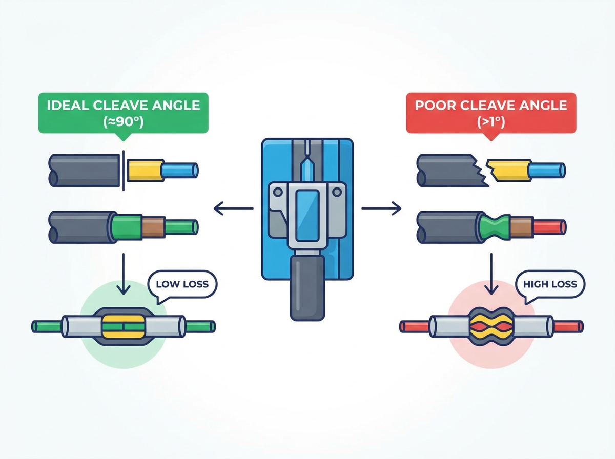
The cleave angle refers to the specific geometric profile of the prepared fiber end-face. In technical terms, it is measured by calculating exactly how far the resulting cut deviates from a mathematically perfect 90-degree perpendicular flat surface. This geometry is arguably the most critical variable in the entire splicing preparation process.
In the telecommunications industry, the universal gold standard dictates that a cleave angle must be 0.5 degrees or less for standard single-mode fiber fusion splicing. Single-mode fibers possess a light-carrying core of only about 9 micrometers in diameter. Any angle exceeding this strict threshold introduces immediate physical barriers. If the angle is too steep, the fusion splicer will struggle to align these microscopic cores accurately during the arc discharge.
Modern fusion splicers actively monitor this tolerance. Equipped with high-resolution microscopic cameras and advanced profile alignment systems, they inspect both fiber ends across the X and Y axes before firing the electric arc. If the software calculates an angle greater than the pre-set threshold, the machine will issue an error warning and halt the process. Visually, a good cut appears on the monitor as a perfectly flat, mirror-smooth vertical line. In contrast, a bad cut may display a lip, a roll-off, or a jagged hackle resembling a mountain range.
To fully grasp why end-face geometry is so critical, one must look at the optical physics of splice loss. Light pulses travel through the microscopic core of the fiber via total internal reflection. Any physical impurity, geometric barrier, or axial misalignment at the splice junction causes light to scatter or escape into the cladding. This escaping light is measured as attenuation, or insertion loss, in decibels.
When two fibers featuring poor cleave angles are placed into the splicer V-grooves, they cannot sit flush against one another. Instead of a flat-to-flat meeting, the angled faces create microscopic wedge-shaped air gaps. As the splicer motors push the fibers together during the stuffing phase, these angled faces act like ramps. They slide against each other. This physically forces the 9-micrometer cores out of perfect alignment just milliseconds before the electrodes fire. The inevitable result is an offset core pathway and a massive spike in signal loss.
Furthermore, jagged edges and severe angles cause light to reflect backward toward the transmitter. This phenomenon is known as optical return loss. It can severely degrade high-speed digital transmissions and destabilize sensitive laser transmitters in the optical line terminal. While modern splicers use a pre-arc to clean micro-dust and slightly round the fiber edges, they are bound by the laws of physics. They cannot melt a 2-degree angle back into a flat surface. They also cannot fill in missing chunks of shattered glass.
Even when equipped with top-tier equipment, human error remains the leading cause of high splice loss. Avoiding these empirically proven field mistakes will drastically improve your first-time splice success rate.
The most frequent operational error is failing to clean the bare fiber before cutting it. After stripping the acrylic coating, microscopic debris and coating residue remain stuck to the glass. If you do not wipe the fiber with 99 percent pure isopropyl alcohol and a lint-free wipe beforehand, that debris transfers directly onto the rubber gripping pads and the precision blade. Dirt on the pads causes the fiber to sit unevenly. Dirt on the blade prevents a clean score.
Tungsten carbide blades are incredibly hard, but they are not invincible. Repeatedly scoring glass on the exact same micro-spot eventually dulls the cutting edge. When the blade becomes dull, it crushes the delicate glass rather than scoring it cleanly. This blunt force leads to shattered end-faces and the dreaded fiber not cleaved error on your monitor.
Placing the fiber crookedly across the V-groove or measurement ruler guarantees an angled cut. The glass strand must be placed exactly perpendicular to the blade path. If it is seated at even a slight diagonal, the resulting score and break will inherit that diagonal geometry. This easily exceeds the 0.5-degree limit.
Precision optical tools require a delicate, deliberate touch. Slamming the lid or striking the slider mechanism with excessive force introduces violent mechanical shock to the glass. Instead of allowing the engineered tension mechanism to smoothly propagate the micro-crack, the shockwave shatters the fiber. This leaves jagged edges and asymmetrical lips.
The rubber clamping pads are responsible for holding the fiber perfectly still during the score and break process. Over time, these pads accumulate environmental dust, finger oils, and microscopic glass shards. When the pads lose their friction, the fiber experiences microscopic twisting or slipping at the exact moment the blade strikes. This creates a spiral-like break and severe roll-off.
Many modern devices feature an automatic scrap collection bin. Allowing this bin to overfill causes discarded shards to back up into the internal mechanism. These hazardous splinters can lodge under the blade carriage. They physically obstruct the blade path or scratch the next fiber you attempt to prepare.
Not all cutting tools are manufactured to the same rigorous tolerances. Relying on a cheap, basic mechanical fiber cleaver for single-mode fusion splicing is a recipe for failure. Single-mode deployments demand precision equipment specifically engineered to maintain strict alignment standards.
Mastering the physical operation of your equipment requires mechanical consistency and a keen awareness of environmental variables.
First, adopt the smooth and steady technique. Whether you are using a single-step automated button or a manual slider model, the application of force must be linear. Apply gentle, steady pressure without stopping halfway across the track. Let the engineered spring tension perform the heavy lifting of fracturing the glass.
Proper stripping length is equally vital to your success. Always consult your fusion splicer technical manual for the required cleave length. This typically ranges from 10mm to 16mm depending on the sheath clamp design. Use the ruler integrated into your tool to align the edge of the stripped coating precisely. A cut that is too long will cause the bare glass to hit the electrodes. A cut that is too short will prevent the splicer motors from successfully bridging the gap.
In addition, environmental control plays a surprisingly large role. Glass optical fibers are highly sensitive to temperature and humidity shifts. In freezing environments, the glass becomes brittle, increasing the likelihood of shattering. In high humidity, condensation can form on the blade, causing the fiber to slip. Whenever possible, perform your splicing operations in a climate-controlled splicing tent or trailer.
Finally, experienced technicians rely heavily on the listen for the click method. A flawless operation produces a very distinct, sharp, and quiet tick sound as the glass fractures cleanly. On the contrary, a dull thud or a crunchy sound is an immediate empirical indicator that the glass has shattered. This prompts the technician to re-strip and re-cut before even checking the splicer screen.
A high-end precision tool is only as reliable as the maintenance it receives. Implementing a strict, proactive maintenance protocol is the most reliable way to prevent sudden spikes in splice loss.
At the end of every shift, a daily cleaning routine should be mandatory. Use a lint-free cotton swab lightly dampened with 99 percent isopropyl alcohol to gently wipe the edge of the circular blade. Never touch the blade with your bare hands. Next, thoroughly clean the upper and lower rubber gripping pads to remove accumulated dust and oils. Wipe down the fiber placement grooves to ensure no rogue glass shards are left behind.
Knowing how and when to rotate the circular blade is a critical field skill. Standard precision blades feature numbered positions around their circumference, usually ranging from 16 to 24 distinct points. As a general rule, you should rotate the blade exactly one position forward after 1,000 to 2,000 operations. For example, move from position 1 to position 2. You should also rotate it immediately if the fusion splicer reports a high cleave angle error on three out of five consecutive attempts.
Once you have rotated the blade through all available positions, the consumable is not necessarily dead. You can adjust the blade height slightly upward to expose a fresh cutting surface. This effectively allows you to cycle through the numbers again. However, refer strictly to the manufacturer calibration manual for this step. Raising the blade too high will snap the fiber prematurely.
Lastly, safe storage is paramount. Never toss these delicate instruments loosely into a heavy canvas tool bag. The internal carriage operates on microscopic tolerances. Dropping the device or subjecting it to heavy impacts can knock the blade carriage out of alignment. Always store the tool inside its dedicated hard protective case.
Selecting the appropriate equipment directly impacts your daily workflow efficiency and overall network quality. When comparing options, you must understand the distinction between basic mechanical models and precision engineering.
To make the selection process clearer, let us look at a direct comparison between basic tools and professional-grade equipment.
Feature | Basic Mechanical Cleaver | High-Precision Optical Cleaver |
|---|---|---|
Average Cleave Angle | Greater than 1.0 degree | Less than 0.5 degrees |
Blade Material & Life | Standard steel / ~10,000 cuts | Tungsten steel / 36,000 to 48,000 cuts |
Operation Mechanism | Multi-step manual process | Single-step automatic return |
Scrap Collection | Manual disposal required | Automatic scrap bin included |
Best Application | Temporary mechanical repairs | 5G and FTTH single-mode splicing |
For single-mode optical networks, investing in a high-quality fiber cleaving tool is an absolute operational requirement. When evaluating new equipment, look for key features designed to minimize human error. High-end models utilize tungsten steel blades capable of delivering up to 48,000 precision cuts. Auto-return mechanisms automatically slide the blade back into position after every cut, completely eliminating the need for manual tracking. Automatic scrap collection bins safely dispose of hazardous shards, protecting both the operator and the internal mechanics.
Ultimately, the preparation phase acts as the strict gatekeeper of overall fusion splice quality. A poor, angled cut guarantees an unacceptable splice loss, rendering even the most expensive fusion splicer completely ineffective. By treating your cutting equipment with the utmost respect and care, you safeguard the integrity of the entire optical link.
Consistent daily maintenance, proactive blade rotation, and refined physical technique will drastically reduce signal degradation. This disciplined approach saves countless hours of troubleshooting, prevents expensive rework, and ensures a highly reliable fiber optic network. If you are struggling with inconsistent splice results, it is time to upgrade your toolkit. Explore the high-precision fiber cleavers available at Skycom to find the perfect engineered solution for your next field deployment. Watch your splice loss readings drop to near-zero.
For single-mode fiber fusion splicing, an acceptable cleave angle is strictly 0.5 degrees or less. Angles higher than this threshold cause severe core misalignment. This results in high insertion loss, excessive reflectance, or completely failed splices.
A premium tungsten steel blade lasts for approximately 36,000 to 48,000 total cuts depending on height adjustments. However, you should rotate the blade to a new numerical position every 1,000 to 2,000 cleaves. Do this immediately whenever you start noticing consistently high cleave angle warnings on your splicer monitor.
Your fusion splicer displays this error because its internal cameras detect that the cut fiber end-face is not perfectly flat. This is usually caused by a dull cleaver blade, dirt on the rubber gripping pads, or the fiber being placed at a crooked angle during the cutting process.
You cannot fix or repair a bad cleave once the glass is cut. The only solution is to open the splicer, remove the fiber, strip back a new section of the acrylic coating, clean the bare glass thoroughly with alcohol, and perform a brand new cut with your precision tool.
While a bad cut will not permanently break the internal motors, inserting poorly cleaved or shattered fiber leaves microscopic glass debris inside the delicate V-grooves and on the electrodes. This debris ruins future splices and requires deep, meticulous cleaning.
If your device fails to cut the glass, check three main culprits. The blade might be dull and needs rotating to a fresh position. The blade height might be set too low to score the cladding. Finally, the rubber gripping pads might be dirty, causing the fiber to slip during the scoring process.
Always strip and clean the fiber before placing it into the tool. Cleaning the fiber after it has been cut introduces dirt, lint, or alcohol residue to the perfectly flat glass end-face. This inevitably causes a high-loss splice and potential electrode contamination.