Views: 0 Author: Site Editor Publish Time: 2026-10-21 Origin: Site
Are dropped signals or inexplicably slow data speeds ruining your network performance? Picture this scenario. You have just spent days routing a new cable plant. Yet, the transceivers are struggling to communicate. In the telecommunications field, this situation almost always points to a major physical layer problem. Excessive signal loss is usually the culprit. As enterprise architectures rapidly expand to accommodate higher bandwidths, ensuring minimal signal degradation becomes critical for optimal performance.
Fortunately, a reliable testing methodology easily solves this issue. You can utilize an Optical Power Meter and an Optical Light Source. These tools are often combined into a comprehensive diagnostic kit. This equipment helps you pinpoint exactly how much light is escaping your network. In this guide, you will learn the exact testing steps required for professional network certification. Furthermore, we will show you how to measure attenuation accurately. This ensures your infrastructure remains robust and reliable.
Key Takeaways
Preparation is Key: Cleaning your fiber connectors before utilizing your diagnostic equipment is the single most critical step. It prevents false readings and permanent hardware damage.
Setting the Baseline: Always establish a zero reference using the one-jumper method before testing the actual fiber link. This guarantees absolute accuracy.
The Right Tools: Integrating a high-quality testing unit is essential for strict Tier 1 network certification. It must combine both power metering and light generation.
Simple Math: Total attenuation is calculated easily. You simply subtract the received power at the destination from the initial output power of the light source.
Wavelength Matching: Ensure both your transmitting and receiving devices are locked to the exact same wavelength to capture valid measurements.
In telecommunications, fiber optic loss is commonly referred to as attenuation or insertion loss. It is the natural decrease in light power as a signal travels through a glass core. This value is universally measured in decibels. Even in perfectly engineered networks, some degree of light degradation is inevitable. This happens due to the inherent physical properties of the glass itself.
However, excessive loss is typically triggered by external and preventable factors. Common culprits include macrobending from routing cables too tightly around corners. Microbending caused by physical pressure on the jacket is another issue. Dirty end-faces, misaligned splices, and natural distance attenuation also contribute. When light scatters or reflects at these physical fault points, the signal reaching the receiver becomes significantly weakened. It often drops below readable thresholds.
Recent analyses of global fiber deployment trends reveal a massive shift in testing requirements. As enterprise data centers rapidly migrate toward 400G and 800G architectures, the tolerance for signal degradation has shrunk drastically. Strict Tier 1 certification is no longer just a best practice. It is a mandatory requirement for warranty compliance and system integrity. Consequently, field engineers are moving away from piecemeal tools. The industry now demands integrated, automated equipment that seamlessly syncs data to cloud platforms. This shift ensures increasingly tight loss budgets are met precisely. It successfully eliminates the manual calculation errors that previously plagued high-speed network deployments.
Every optical link is designed with a specific loss budget. This metric represents the maximum amount of signal degradation the system can tolerate. If the loss exceeds this limit, the active equipment fails to decipher the transmitted data. Exceeding this loss budget invariably leads to high bit error rates, dropped packets, and unexpected network downtime. Ultimately, it causes transceiver hardware failure.
For IT and telecom professionals, ensuring that insertion loss remains strictly within acceptable limits is a non-negotiable maintenance task. Regular and systematic testing is the only objective way to verify system health. It proves that a cable plant can support high-speed data transmission without compromising long-term reliability.
To measure insertion loss accurately, field technicians rely on specific diagnostic tools. Understanding the distinct function of each component is vital for proper network certification and troubleshooting.
An optical power meter acts as the receiving end of your testing setup. Its primary function is to measure the absolute power of the continuous light signal arriving at the termination point of the cable. This absolute power is typically measured in decibels relative to one milliwatt. Modern meters utilize highly calibrated photodiodes, such as InGaAs for single-mode or Silicon for multimode applications. These sensors detect the precise amount of photonic energy present.
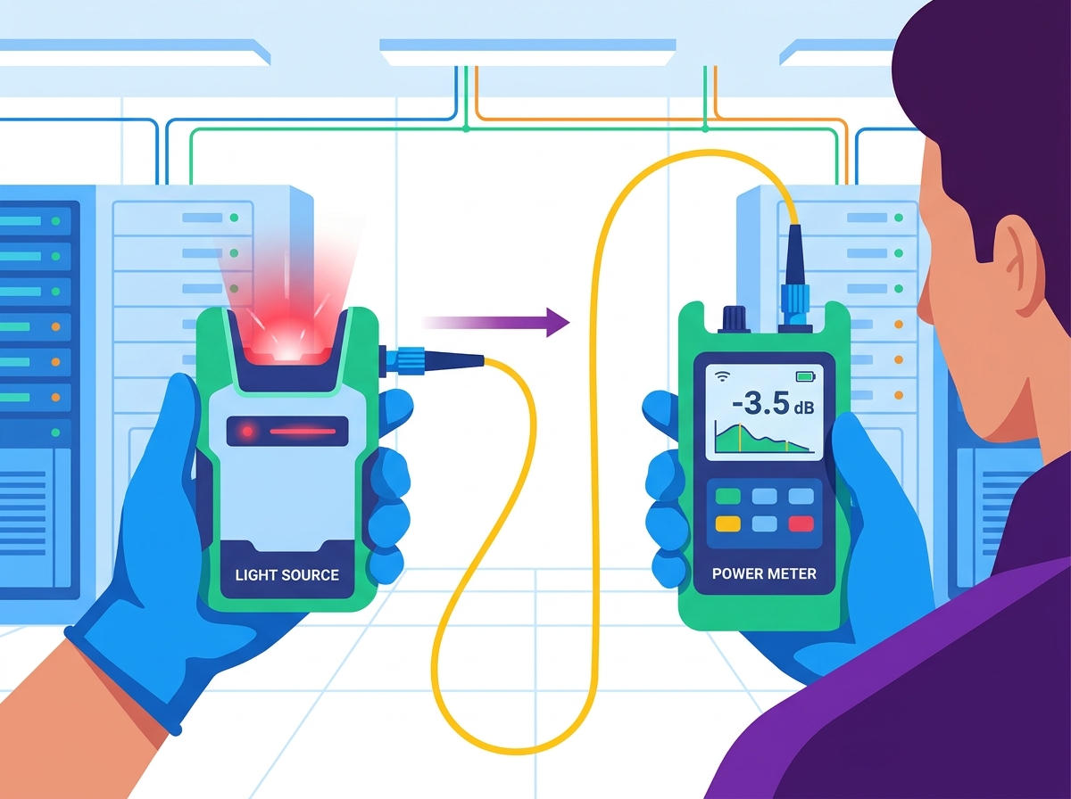
In contrast, the Optical Light Source serves as the transmitting end. It injects a stable, continuous, and mathematically known beam of light into the fiber core. For any test to be valid, the light source must emit light at the exact wavelength that the active network switches will eventually utilize. Common wavelengths include 850nm and 1300nm for multimode fiber. Single-mode infrastructure typically relies on 1310nm and 1550nm.
While you certainly can purchase a power meter and a light source as separate standalone devices, professional technicians typically prefer an Optical Loss Test Set. This device intelligently combines both the power meter and the light source into one cohesive unit. It drastically streamlines the field testing process. Professional-grade units feature a wide measurement range, typically from -70 dBm to +10 dBm. They also support multiple calibrated wavelengths including 850nm, 1300nm, 1310nm, 1490nm, 1550nm, and 1625nm. Investing in field-tested equipment ensures measurement precision, robust durability in harsh environments, and strict compliance with international testing standards.
Industry studies consistently demonstrate that over 85 percent of network failures are directly caused by contaminated end-faces. A single microscopic speck of dust can entirely block the optical signal. Worse, it can permanently scratch the delicate glass upon mating. Therefore, a comprehensive diagnostic kit must include a digital inspection microscope. You also need specialized lint-free wipes, optical-grade cleaning fluid, and a Visual Fault Locator for basic continuity checks.
The foundational methodology for all optical maintenance is simple yet absolute. Inspect, clean, and inspect again. Before any test cables are ever connected, you must use an inspection scope. Meticulously examine the end-faces of your connectors for dust, skin oils, or microscopic scratches. If any contamination is present, utilize a dedicated dry-cleaning tool or a wet-to-dry cleaning method. Immediately inspect the connector again. Never connect a dirty ferrule to your diagnostic equipment. This careless action will transfer debris and permanently damage the sensitive optical ports.
This rigorous preparation extends directly to your hardware as well. Carefully clean the output port of your light source and the detector port of your power meter. Only proceed to establish your testing baseline after verifying that both the hardware ports and the Test Reference Cords are immaculately clean.
You cannot accurately measure the attenuation of a newly installed link without knowing the exact starting power of your light source. Setting a reference effectively zeroes out the inherent loss introduced by the test cables themselves. If you bypass this critical step, your final reading will inadvertently include the attenuation of your reference cords. This leads to a falsely high measurement that may cause a perfectly healthy network to fail certification.
The industry-recommended procedure for establishing this baseline is known as the 1-jumper reference method. To execute this correctly on your diagnostic tools, follow these actionable steps.
First, attach a single, pristine Test Reference Cord directly from the Optical Light Source to the Optical Power Meter. This is your launch cable. Next, power on both devices and allow the laser to stabilize for roughly one to two minutes. Ensure both units are synchronized to the exact same wavelength. Finally, press the zero or reference button on your power meter. The digital display should instantly reset to read exactly 0.00 dB. This indicates that your device is now perfectly calibrated to the output power of that specific laser and jumper cord.
Once the zero reference is established, you must physically connect your equipment to the actual cable plant you intend to certify. Carefully disconnect the reference cable from the power meter only. Under no circumstances should you disconnect it from the light source. Doing so will instantly invalidate your baseline. Next, attach a second high-quality reference cable to the power meter. This is your receive cable. Finally, connect the free ends of both the launch cable and the receive cable to opposite ends of the fiber optic link under test.
With the equipment properly seated across the link, the light source will push a continuous signal through the entire cable run. The number now displayed on your screen represents the total insertion loss of that specific link. It is expressed clearly in decibels. For comprehensive enterprise-grade certification, industry standards often require technicians to test the link at two different wavelengths. You must also test in both directions and meticulously document the results for each phase.
The fundamental physics behind insertion loss measurement relies on a straightforward calculation. Total Loss equals Transmitted Power minus Received Power.
Transmitted power represents the absolute strength of the signal injected into the cable. Received power is the strength of the signal that successfully reaches the destination. Fortunately, modern diagnostic tools perform this complex math automatically when you properly set a zero reference using the 1-jumper method. The final reading on the screen is your definitive loss figure.
Obtaining a loss value is only useful if you know whether that value is acceptable for your specific architecture. To interpret this, you must compare the reading against the calculated loss budget. This budget is the maximum allowable signal attenuation determined by the cable length and the number of connection points.
According to TIA and EIA industry standards, acceptable loss parameters generally dictate that a mated connector pair should lose no more than 0.75 dB. A mechanical or fusion splice should range between 0.1 dB and 0.3 dB. If your device displays a total loss that exceeds your calculated budget, the link formally fails. In such scenarios, technicians must systematically troubleshoot. They start by re-cleaning all connectors, hunting for severe macrobends, or re-splicing segments that exhibit high resistance.
Even seasoned field technicians can encounter anomalous readings if strict testing protocols are ignored. Drawing upon empirical data and common field reports, several procedural errors frequently compromise the integrity of optical measurements.
One of the most prevalent errors is a wavelength mismatch. Fiber optic cables attenuate light differently depending on the signal wavelength. For instance, your light source might be injecting a signal at 1310nm. If your power meter is calibrated to read at 1550nm, the internal photodiode will entirely misinterpret the incoming power level. This oversight results in highly skewed and invalid loss readings. Always double-check that both devices are perfectly synchronized before pressing the reference button.
As previously emphasized, unplugging the launch cable from the light source after setting the zero baseline is a catastrophic procedural mistake. Disconnecting and reconnecting this interface alters the microscopic physical alignment of the glass core. This instantly changes the initial power output. If this happens, you cannot simply plug it back in. You must restart the entire referencing process from scratch.
The accuracy of your measurements is directly proportional to the quality of your test cables. Standard patch cords pulled from a data center rack should never be used to set a reference. Instead, you must use specialized Test Reference Cords. However, even these cords degrade over time with repeated mating cycles. Using a scratched or worn cord will introduce artificial loss into your measurements. This makes a perfectly healthy network appear as though it is failing on your reliable fiber tester. Inspect and replace your reference cables regularly.
When outfitting a toolkit for optical network maintenance, professionals often debate between utilizing an Optical Loss Test Set versus an Optical Time-Domain Reflectometer. While both instruments are indispensable, they serve fundamentally different diagnostic purposes.
Feature | Optical Power Meter & Light Source | OTDR |
|---|---|---|
Primary Function | Measures total end-to-end insertion loss | Locates specific faults and measures distance |
Certification Level | Tier 1 | Tier 2 |
Accuracy for Total Loss | Extremely High | Moderate |
Cost & Complexity | Cost-effective, easy to use | Expensive, requires advanced training |
Best Use Case | Routine validation, standard compliance | Advanced troubleshooting, pinpointing breaks |
The telecommunications industry categorizes certification into two distinct tiers. Tier 1 testing involves measuring the total end-to-end insertion loss of a link. This is accomplished using a power meter and light source. It is the foundational requirement for nearly all enterprise networks. Conversely, Tier 2 testing supplements Tier 1 by providing a graphical representation of the entire cable run using an OTDR. This device injects high-power light pulses and measures the backscatter. It helps pinpoint the exact physical location of faults, splices, and breaks kilometers away.
For basic loss measurement, routine validation, and standard compliance certification, the power meter and light source combination is heavily preferred. It is faster, significantly more cost-effective, and provides a much more accurate measurement of the overall insertion loss that the active transceivers will actually experience. An OTDR should primarily be reserved as an advanced troubleshooting tool. It is deployed only when a Tier 1 test reveals a failing link.
Selecting the appropriate diagnostic equipment directly impacts your team efficiency and measurement accuracy. When evaluating options, consider these critical parameters to ensure you get the best return on investment.
Specifically, check the dynamic range first. A robust meter should handle signals as low as -70 dBm for long-haul networks and up to +10 dBm for standard telecom applications. Second, verify wavelength compatibility. Ensure the device natively supports standard telecom wavelengths like 850nm, 1300nm, 1310nm, and 1550nm. Third, look for integrated physical features. An Optical Loss Test Set that combines a power meter, light source, and a Visual Fault Locator into a single rugged chassis significantly reduces the amount of gear technicians must carry. Investing in a high-quality fiber tester with robust battery life and a shock-proof exterior is essential for demanding field environments.
Acceptable loss is not a static number. It is entirely dependent on the specific architecture of your cable plant. Generally, industry standards dictate that optical connectors should exhibit no more than 0.75 dB of loss per mated pair. Mechanical or fusion splices should range between 0.1 dB and 0.3 dB. Furthermore, the optical glass itself will naturally attenuate the signal over distance. To determine if a reading is acceptable, you must calculate the total theoretical loss budget of your specific link based on its length and the number of passive components. Then, ensure your measured reading falls below that threshold.
Calculating a loss budget involves simple addition. You multiply the total length of the fiber by the standard attenuation rate for that specific wavelength. For example, single-mode fiber at 1310nm loses about 0.4 dB per kilometer. Next, add the estimated loss for all connectors in the link, calculating 0.75 dB per pair. Finally, add the estimated loss for all splices, calculating 0.3 dB per splice. The sum of these three factors is your total maximum loss budget.
High insertion loss is predominantly caused by physical contamination or mechanical stress. The most common culprit is a dirty connector end-face. Even microscopic dust particles scatter the light beam. Other major causes include severe macrobends where the cable is bent beyond its minimum radius, poor fusion splices, misaligned connector mating, and physical damage to the fiber core itself.
A power meter can be used in isolation if your sole objective is to verify the output power of active networking equipment, such as a core switch or an optical transceiver. In this scenario, the active equipment acts as the transmitter. However, if your objective is to measure the insertion loss of a dark or inactive cable run, a standalone meter is insufficient. You absolutely must utilize a controlled, stabilized light source to inject a known quantity of light into the cable. This allows you to calculate the subsequent attenuation accurately.
Maintaining the precision of optical measurement tools requires strict adherence to factory calibration schedules. The internal photodiodes in receivers and the laser diodes in transmitters can experience minute drifts in accuracy over time. This happens due to environmental factors, temperature fluctuations, and regular physical usage. Most major equipment manufacturers and industry standards bodies strongly recommend sending your devices to a certified laboratory for formal calibration every 12 months. This ensures your certifications remain valid.
It is critical to distinguish between dBm and dB. When measuring absolute optical power in dBm, a negative reading is entirely normal. It simply indicates that the power level is less than one milliwatt, which is standard for telecom signals. However, if you are measuring relative loss in dB and the device displays a negative number, this indicates a procedural error. A negative loss implies the signal gained power as it traveled, which is physically impossible in a passive cable. This error almost always occurs if the baseline reference was set incorrectly, or if a dirty connector was cleaned after the initial reference baseline was established.
Understanding the distinction between these two units is fundamental to field testing. The unit dBm is an absolute unit of measurement that quantifies the actual power of the optical signal. Zero dBm is exactly equal to one milliwatt of optical power. Conversely, dB is a relative unit of measurement used to express a ratio or a difference between two power levels. In the context of this guide, dB is used to express the amount of light lost as the signal travels from the source to the destination.
Measuring fiber optic loss is a highly straightforward process when you adhere strictly to the proper methodology. By understanding the physics of light attenuation and mastering the one-jumper reference method, technicians can confidently certify any network infrastructure. Ultimately, accurate results rely heavily on the quality of your testing equipment and the pristine cleanliness of your physical connections. For engineers looking to upgrade their daily toolkits, exploring professional solutions like a comprehensive fiber tester kit is a smart investment. Reliable equipment ensures your networks run consistently at peak performance. Equip your team with precision tools today to avoid costly downtime and maintain your infrastructure with absolute confidence.