Views: 0 Author: Site Editor Publish Time: 2026-10-07 Origin: Site
Did your recent fiber splice fail the final Optical Time-Domain Reflectometer test? Standing in a cold, muddy trench only to discover unacceptably high signal loss on a newly sealed enclosure is incredibly frustrating. High attenuation ruins network efficiency. It creates expensive rework and delays project handovers.
Thermal joining remains the most reliable method for connecting optical fibers. However, it demands extreme precision. Microscopic errors cause massive decibel drops. We will break down the exact causes of signal degradation in this guide. We categorize them into intrinsic fiber mismatches and extrinsic operational errors. Mastering field-proven preparation techniques and utilizing a high-quality fiber fusion splicer allows technicians to consistently achieve near-zero loss.
Intrinsic vs. Extrinsic: High loss originates from either intrinsic fiber mismatches or extrinsic operational errors like poor cleaves.
Preparation is Everything: Industry data suggests over 80 percent of high loss issues stem from improper cleaning and poor cleaving techniques.
Equipment Matters: Regular maintenance and routine arc calibration are non-negotiable requirements for consistent results.
The Right Tool: Investing in an advanced core-alignment machine drastically reduces the margin of error.
The telecommunications landscape is shifting rapidly. With the aggressive rollout of 5G networks and hyperscale data centers, optical link budgets are tighter than ever. A decade ago, a 0.10 decibel loss might have passed inspection. Today, network engineers demand near-perfect joints to support massive bandwidth requirements. This industry-wide push for lower attenuation means field technicians must upgrade both their skills and their optical network equipment to stay competitive.
It is crucial to establish a baseline of what constitutes an acceptable splice before troubleshooting high loss.
Splice loss refers to the amount of optical power lost at the point where two optical fibers are joined together. We measure this in decibels. Because the decibel scale is logarithmic, even a seemingly small numerical increase represents a significant drop in optical power. Every single joint contributes to the overall optical link budget in long-haul networks. If the cumulative attenuation exceeds the allocated budget, the signal will not reach the receiver with enough clarity. This leads to network downtime or the need for expensive optical amplifiers.
Different types of fiber carry different acceptable loss thresholds. The telecommunications industry generally adheres to strict benchmarks. For Single-Mode Fiber, the official standard allows up to 0.30 decibels per splice. Modern technicians equipped with advanced tools should consistently target an insertion loss of 0.01 to 0.02 decibels. Conversely, Multi-Mode Fiber is slightly more forgiving due to its larger core. It typically averages around 0.01 decibels in practical field applications.
Modern splicing machines utilize advanced Profile Alignment Systems. High-resolution cameras capture the X and Y axes of the fiber core before, during, and after the arc discharge. The internal software calculates an estimated loss by analyzing the alignment and detecting any core deformation after the melt. Nevertheless, this is strictly an optical estimation. Technicians must always verify the link using an OTDR to obtain the true attenuation value.
Intrinsic factors are physical characteristics inherent to the manufacturing of the glass itself. Understanding them is essential for managing expectations and effectively troubleshooting failed tests.
Light does not exclusively travel through the physical core in single-mode fibers. A small portion travels in the inner cladding. The total area occupied by the light is called the Mode Field Diameter. The diameters may not match perfectly when splicing fibers from different manufacturers. Specifically, when light passes from a fiber with a larger diameter into one with a smaller diameter, a portion of the light scatters at the junction. This results in unavoidable intrinsic loss.
The core is occasionally not perfectly centered within the 125-micron cladding during the fiber manufacturing process. This phenomenon is known as a core concentricity error. If a technician uses a basic cladding-alignment machine, the hardware will align the outer edges of the cladding perfectly. However, the off-center cores will remain misaligned. This physical offset restricts the light path and causes high insertion loss.
Advanced hardware utilizes core-alignment technology to combat these manufacturing discrepancies. The internal cameras focus strictly on the light-carrying core instead of looking at the outer cladding. The internal multi-axis motors adjust the fiber positions to align the cores precisely. This happens regardless of cladding irregularities. While this minimizes the loss caused by concentricity errors, loss caused by severe diameter mismatches cannot be entirely eliminated by any machine.
Unlike intrinsic mismatches, extrinsic factors are entirely within the technician control. These are the most common, yet highly preventable, errors made in the field during daily operations.
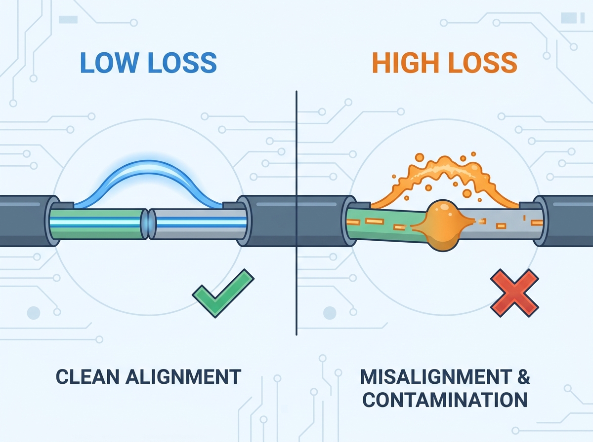
A flawless splice requires a flawless cleave. The end-face of the fiber must be cut at an angle as close to 90 degrees as possible. We typically allow for less than 0.5 degrees of deviation. The resulting face may be angled, chipped, or jagged if the cleaver blade is dull. When the hardware attempts to melt these irregular faces together, the glass fuses unevenly. This creates microscopic air pockets or core shifts that severely degrade the signal.
Dust, dirt, moisture, and natural oils from human fingers are the greatest enemies of a good splice. Furthermore, failing to remove all the acrylate coating residue during the stripping process leaves microscopic debris on the glass. This dirt burns instantly when the machine fires its electrical arc. The combustion creates carbon deposits and microscopic bubbles trapped inside the molten glass. Consequently, you get exceptionally high optical loss.
The thermal joining process relies on an electrical arc generated between two tungsten electrodes to melt the silica glass. Silica vapor from the melted fibers deposits onto the tips of these electrodes over time. The electrical arc becomes unstable or weak as these deposits build up. A weak arc fails to melt the glass completely. This leads to a cold splice. Cold splices exhibit high attenuation and are physically fragile.
Achieving near-zero loss requires a disciplined approach. Follow this highly actionable troubleshooting guide to refine your field preparation process.
The order of operations is absolutely critical. You must always clean the fiber before cleaving it. First, remove the protective coating using a calibrated stripping tool. Next, wipe the bare glass with a lint-free wipe soaked in 99 percent isopropyl alcohol. You should hear a distinct squeak indicating the glass is perfectly clean. Finally, place the clean fiber into the precision cleaver. Never wipe the fiber after cleaving. Doing so will drag microscopic lint and dirt across the core.
The electrical arc is highly sensitive to environmental conditions. Changes in ambient temperature, humidity, and barometric pressure alter the air density. This in turn changes the intensity of the plasma arc. Technicians should run an arc calibration test at the beginning of every shift. The machine will perform a series of test arcs on scrap fiber and automatically adjust the electrical current to ensure an optimal melt.
Do not wait for a splice to fail before checking your electrodes. Most high-quality electrodes have a lifespan of 3000 to 5000 arc discharges. Modern equipment features an internal arc counter and will issue a warning when it is time for a replacement. Swap the electrodes out immediately if you notice a buzzing sound during the arc.
The V-grooves are the tiny channels that hold the delicate fibers in place. If a microscopic speck of dust settles in the V-groove, it forces the fiber to sit at an angle. This makes alignment impossible. Use a lint-free swab moistened with isopropyl alcohol to gently sweep the V-grooves. Similarly, clean the objective lenses carefully. The software cannot align the cores accurately if the internal cameras cannot see the fiber clearly.
A precision cleaver blade is a consumable item. Most circular blades feature 16 numbered positions. Each position is good for approximately 1000 to 2000 cleaves. It is time to rotate the blade to the next position if you begin noticing consistently high cleave angles. Replace the blade entirely once all positions are used.
Isolate your workspace from harsh elements whenever possible. Wind can blow dust onto your prepared fibers or disrupt the electrical arc during fusion. Direct sunlight can interfere with the optical cameras. Utilizing a splicing tent drastically reduces environmental variables.
Routine maintenance goes beyond achieving low splice loss. It actively protects your capital investment.
Implementing a strict maintenance checklist ensures your equipment remains in peak condition. Technicians should clean the V-grooves and wipe down the fiber clamps with alcohol on a daily basis. Weekly maintenance should include carefully cleaning the objective lenses with dry swabs.
Ignoring basic cleaning creates a compounding domino effect. The fiber will not sit flat if debris accumulates in the V-grooves. The machine micro-stepping motors will then have to overwork to push the misaligned fiber into place. This constant mechanical strain degrades the motor gears over time. A simple two-minute daily cleaning routine prevents these costly breakdowns.
The micro-task of splicing directly impacts macro-business goals in the broader context of telecommunications.
A signal may pass through dozens of joint enclosures before reaching its destination in a long-haul optical network. That extra loss compounds rapidly if a technician accepts a 0.10 decibel loss on every splice instead of pushing for 0.02 decibels. This cumulative signal degradation reduces overall bandwidth capacity.
Investing time in proper technique and capital in premium equipment yields a massive Return on Investment. A single failed splice discovered during final testing requires dispatching a technician back to the field. This rework costs hundreds of dollars in labor and delays project handovers. Doing it right the first time eliminates rework and maximizes network uptime.
A skilled technician is only as good as their tools. Upgrading your equipment is often the most direct route to eliminating high splicing loss.
You must choose between cladding alignment and core alignment technologies when selecting a machine. Cladding alignment systems use 4 motors to align the outer diameter of the fiber. They are generally more affordable and suitable for short-distance networks. In contrast, core alignment machines use 6 motors and advanced imaging to look past the cladding. They align the actual light-carrying cores. A core alignment device is absolutely essential for long-haul networks to compensate for intrinsic fiber errors.
Feature | Core Alignment | Cladding Alignment |
|---|---|---|
Motor Configuration | 6 Motors | 4 Motors |
Alignment Focus | Fiber Core | Outer Cladding |
Typical SMF Loss | 0.01 to 0.02 decibels | 0.03 to 0.05 decibels |
Best Application | Long-haul, DWDM, High-speed SMF | Short-distance, FTTx, MMF |
Look for features designed to automate precision and reduce human error when evaluating new hardware. For instance, industry-leading advanced core-alignment machines feature 6-motor technology capable of achieving a typical splice loss of just 0.02 decibels for single-mode fibers. You want a machine that offers rapid 8-second splicing and 15-second heating times to keep field operations moving efficiently. High-resolution magnification of 300x or higher allows technicians to visually inspect the core alignment. Additionally, rugged IP-rated durability ensures the machine survives harsh field environments. A high-capacity 5200mAh battery is also crucial for sustaining long shifts without power interruptions.
It may be time to invest in modern technology if you are struggling with inconsistent results. Explore the high-performance solutions from Skycomtech. Their equipment is designed for uncompromising accuracy, robust durability, and ease of use in the field.
High fusion splicing loss is rarely a mystery. It is almost entirely preventable through a combination of understanding fiber physics, maintaining strict cleanliness, and utilizing the correct technology. Technicians can systematically eliminate errors by mastering the fundamental strip, clean, cleave process.
Remember that a meticulously prepared fiber still requires a highly calibrated machine to achieve a perfect melt. You can ensure your fiber optic networks remain efficient and reliable by pairing stringent preparation standards with high-quality equipment. Evaluate your current toolkit today to ensure you are ready for your next critical network deployment.
The maximum acceptable loss is governed by specific network design parameters and the type of optical fiber being utilized. While older standards allowed up to 0.30 decibels, modern network engineering rarely tolerates this. Engineers typically mandate a target goal of 0.01 to 0.02 decibels for Single-Mode Fiber deployed in long-haul networks. For Multi-Mode Fiber, the acceptable loss typically averages around 0.01 decibels. Technicians should always consult the specific project optical link budget documentation.
Electrodes should be replaced every 3000 to 5000 arc discharges as a general industry standard. Most modern machines feature an internal counter that tracks the exact number of arcs and will issue a proactive maintenance warning. However, the electrodes must be replaced immediately if you observe a visibly rounded tip or experience repeated weak arc errors. A buzzing sound during the melt is also a clear indicator of electrode wear.
No, a splicing machine cannot fix or adequately compensate for a bad fiber cleave. Some advanced core-alignment machines can slightly compensate for minor angles between 0.5 and 1.0 degrees by adjusting the arc power. However, a severely jagged cleave will cause catastrophic failure. The uneven glass volume melts asymmetrically, distorting the internal core and causing massive signal scattering. The only correct solution is to strip, clean, and re-cleave the fiber.
A fiber mismatch error occurs when the internal imaging software detects a significant physical or optical discrepancy between the two fiber strands. This frequently happens when attempting to join two different types of fiber like Single-Mode to Multi-Mode. Alternatively, this error is commonly triggered by severe dirt on the glass cladding or debris inside the V-grooves. Always re-clean the fibers and the machine before assuming the cables are incompatible.
A negative splice loss, often called a gainer, is an optical illusion created by the OTDR. This occurs when you splice two fibers with different backscatter coefficients. The second fiber scatters more light back to the OTDR than the first fiber, making it appear as though the signal gained power at the splice point. To find the true loss, you must test the link from both directions and average the two readings.
The only way to fix a high loss splice is to physically break the joint and start over. You cannot re-burn or re-arc an already completed splice to improve it. Doing so will only deform the glass further and increase attenuation. You must open the splice tray, cut the fiber back to fresh glass, and meticulously repeat the strip, clean, and cleave process before fusing the fibers again.