Views: 0 Author: Site Editor Publish Time: 2026-10-28 Origin: Site
Investing in a reliable fiber optic fusion splicing machine stands as one of the most consequential operational decisions for any telecommunications contractor, network engineer, or IT infrastructure professional. The right tool ensures near-invisible splice loss and rock-solid network reliability. Conversely, deploying the wrong equipment inevitably leads to costly rework, severe signal degradation, and delayed project timelines.
With a myriad of devices flooding the market today, the most critical technical choice you will face involves selecting the appropriate alignment technology. Stripping back the marketing jargon reveals a simple truth. The core functionality of your equipment entirely dictates its field performance.
This comprehensive guide breaks down the fundamental technical differences, operational advantages, limitations, and ideal use cases for the two dominant technologies shaping the industry. These are core alignment and cladding alignment fusion splicers. Whether you are constructing a massive long-haul backbone network or rapidly deploying fiber to the home, this objective comparison will help you evaluate your exact requirements and choose the optimal splicing equipment for your specific environment.
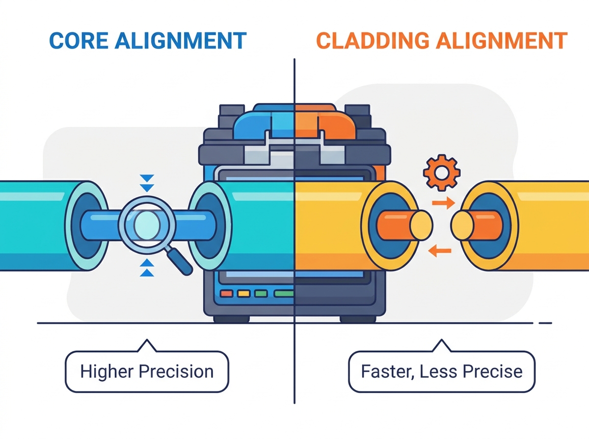
Core Alignment Technology: These advanced devices utilize sophisticated imaging systems to align the actual silica cores of the fibers. This precision results in the lowest possible splice loss, typically hovering around 0.02dB. Consequently, they remain the undisputed standard for long-haul, high-speed backbone networks where optical loss budgets are strictly limited.
Cladding Alignment Technology: Often relying on a fixed V-groove mechanical system, these machines align the outer surface of the fiber. They are generally more compact, highly budget-friendly, and perfectly suited for short-distance networks like local area networks and enterprise environments.
Cost versus Performance Matrix: Core alignment machines require a steeper initial capital investment but deliver unmatched optical precision. In contrast, cladding models offer a cost-effective, highly durable alternative tailored for rugged outdoor field work.
Project-Driven Selection: Your final equipment choice should be dictated by your project's specific optical loss budget, the physical age and concentricity of the fiber being spliced, and the environmental conditions of your deployment site.
A fusion splicing machine acts as a highly specialized instrument designed to permanently join two optical fibers end-to-end. Picture a field technician perched in a bucket truck. They strip the 250-micron protective coating. They wipe the bare glass with 99 percent isopropyl alcohol. Finally, they precisely cleave the ends. At this exact moment, the machine takes complete control. It fires a carefully calibrated electric arc to melt the silica glass. This fuses the two fibers together to create a seamless optical path. The ultimate goal remains simple but demanding. Light signals must pass through the splice point with near-zero reflection or attenuation.
For light to transmit efficiently, the two glass ends must be aligned with microscopic exactness. A standard single-mode fiber core has a diameter of merely 9 micrometers. This is roughly one-tenth the thickness of a human hair. Even a fractional offset at this microscopic scale causes significant signal loss, compromising the integrity of the entire network span.
To achieve this necessary optical perfection, the telecommunications industry relies on two primary mechanical methods. Grasping the mechanical and optical distinctions between core and cladding systems serves as the foundational step in making an informed procurement decision.
Core alignment systems represent the absolute pinnacle of fusion splicing precision. These machines operate using a sophisticated mechanism known as the Profile Alignment System. Rather than relying on the physical outer dimensions of the fiber, this system employs multiple high-resolution cameras and a complex arrangement of precision stepper motors. High-end advanced fusion splicer equipment typically utilizes six motors to view and manipulate the fiber along the X, Y, and Z axes.
By illuminating the fiber ends, the cameras capture the refraction of light passing through the glass. This allows the internal image processing algorithms to identify the exact position of the actual light-carrying silica core. The motors then dynamically adjust the fibers until the internal cores are perfectly aligned. They completely ignore whether the outer cladding is perfectly concentric or slightly misshapen.
The primary advantage of this technology lies in its ability to consistently achieve ultra-low splice loss. A standard core-to-core splice typically yields an attenuation of just 0.02dB. Because the machine actively seeks the core, it handles older, legacy fibers or fibers from different manufacturers exceptionally well. It seamlessly compensates for any manufacturing inconsistencies in the outer cladding.
Furthermore, industry-leading models are engineered for efficiency. Modern core alignment units boast rapid 8-second splice times and 25-second heating cycles, powered by high-capacity 5200mAh batteries capable of exceeding 200 continuous splice and heat cycles. However, this microscopic precision introduces specific trade-offs. Core alignment machines demand a significantly higher upfront financial investment. More importantly, the sensitive optical components require meticulous maintenance. A single microscopic speck of dust settling on the internal lenses can blind the alignment algorithms, leading to machine errors or high-loss splices.
Because of their unmatched optical accuracy, core alignment machines serve as the mandatory standard for long-haul telecommunications, high-capacity backbone transport rings, and trunk lines. Any infrastructure project characterized by highly restrictive optical loss budgets over distances exceeding tens of kilometers necessitates the use of core alignment technology to ensure data integrity.
Taking a more mechanical approach, cladding alignment splicers operate on a fixed V-groove system. These machines strip away the complexity of six-motor profiling, typically utilizing just two to four motors. Instead of using complex imaging algorithms to hunt for the inner core, the technician places the stripped and cleaved fibers directly into precision-machined V-shaped grooves.
The operational logic here is straightforward. The machine assumes that the fiber core is perfectly centered within the outer 125-micron cladding. By physically aligning the outer diameter of the two fibers within the rigid geometry of the groove, the machine aligns the internal cores by proxy. While cameras are still utilized to inspect the cleave angle and estimate post-splice loss, the physical alignment relies entirely on the mechanical V-groove and the manufacturing quality of the fiber itself.
Cost-effectiveness stands out as the most significant advantage of cladding alignment technology. The reduction in complex optics and motors lowers the barrier to entry, making these machines highly accessible for smaller contractors. This simplified mechanical design yields a smaller physical footprint, lighter carry weight, and exceptionally fast boot and splice cycles. They are incredibly robust, easily shaking off the vibrations and bumps typical of demanding field environments.
In contrast, the main drawback is a marginally higher average splice loss. This typically hovers around 0.05dB. Because the machine aligns the exterior surface, any concentricity error originating from the fiber manufacturing process directly translates into a core offset during the splice. This naturally increases optical attenuation.
These devices shine in environments where a slightly higher splice loss is mathematically acceptable. They dominate the landscape for fiber to the home deployments, localized network installations, data center cross-connects, and short-haul drop cables. When the total transmission distance remains short, a 0.05dB loss at the splice point is easily absorbed by the network loss budget without degrading the end-user bandwidth experience.
To make the procurement process clearer, we have compiled a direct comparison of the critical technical specifications and field performance metrics. Reviewing this data helps contractors match the right tool to their specific operational demands.
Feature | Core Alignment | Cladding Alignment |
|---|---|---|
Alignment Method | Optics & 6 Motors finding the silica core | Fixed V-Groove & 2 to 4 Motors aligning the exterior |
Average Splice Loss | 0.02dB | 0.05dB |
Fiber Compatibility | Excellent for legacy, mismatched, or poor concentricity fiber | Requires high-quality, modern fiber with good concentricity |
Capital Investment | High | Low to Moderate |
Ideal Use Case | Long-haul, DWDM, Tier-1 Backbone | FTTx, LAN, Short-haul drops |
The financial disparity between various optical fiber fusion splicer types requires careful consideration. Core alignment models represent a premium capital expenditure, often costing twice as much as V-groove alternatives. Calculating your return on investment demands looking beyond the initial sticker price. If your firm bids on municipal backbone projects or tier-1 telecom contracts, the specifications will legally mandate the ultra-low loss that only core alignment can provide. Attempting to use inferior equipment will result in failed certification tests and expensive rework. For high-volume residential contractors, purchasing multiple cladding machines allows for deploying larger crews simultaneously, drastically accelerating revenue through sheer volume.
Physical footprint acts as a daily reality check for field technicians. Imagine balancing in a bucket truck swaying in a steady breeze, or crouching in a muddy, cramped trench. In these scenarios, the ultra-compact, lightweight design of a cladding alignment machine provides a massive operational advantage. While modern core alignment machines have shed considerable bulk over the last decade, cladding machines still hold the definitive edge in handheld portability.
Looking at recent industry shifts, the rapid expansion of 5G networks and rural broadband initiatives has profoundly impacted equipment preferences. Analysts note a surging market demand for highly portable, ruggedized models that can endure harsh outdoor environments without sacrificing operational speed. This macro trend heavily favors V-groove technologies for last-mile drops.
Concurrently, the explosion of artificial intelligence data centers and hyperscale facilities requires ultra-dense fiber counts. This pushes operators to demand absolute optical perfection to maximize bandwidth over short but critical links. Consequently, this drives continuous innovation in automated core alignment profiling. This bifurcation in the market underscores that manufacturers are increasingly tailoring their devices to specific deployment environments rather than attempting a universal approach.
Laboratory specifications rarely reflect the grueling realities of field splicing. Technicians constantly battle wind-blown dust, high humidity, and extreme temperature fluctuations. Dust remains the undisputed enemy of any splicing operation. In a core alignment machine, if microscopic debris settles on the objective lenses, it can completely blind the cameras. The machine will fail the alignment process repeatedly until the technician stops to perform a meticulous cleaning routine. This often requires setting up a controlled splicing tent.
Interestingly, the simpler mechanics of a clad alignment fusion splicer can become a distinct advantage in dirty environments. While debris sitting in a V-groove will absolutely cause a bad splice, rectifying the issue is a purely physical task. Swabbing a mechanical V-groove with a lint-free stick and alcohol is a fast, straightforward process taking mere seconds. Attempting to safely clean the delicate internal mirrors and lenses of a core alignment system while standing on a dusty roadside is far more stressful and time-consuming. For rapid outdoor drop installations where speed is critical, the rugged, less-fussy nature of a cladding splicer earns high praise from field crews.
Balancing initial capital expenditure with operational requirements is an exercise in practical risk management. To make the most informed decision, contractors must evaluate three primary field criteria before issuing a purchase order.
The golden rule of equipment selection involves matching the machine capabilities to the network distance. Are you splicing single-mode fiber over distances exceeding 20 kilometers, or working on Dense Wavelength Division Multiplexing networks? If so, core alignment is non-negotiable. If you are terminating multimode fiber inside a single commercial building or running short drops from a street cabinet to a home, a cladding alignment machine will execute the job flawlessly at a fraction of the cost.
Consider the physical infrastructure you are tasked with handling. Modern optical fibers are manufactured to incredibly tight tolerances, meaning the core is almost perfectly centered. Cladding splicers perform exceptionally well with new fiber. However, if your contracts involve repairing legacy networks built decades ago, you will encounter older fibers with poor concentricity. Forcing the exteriors of these older fibers to match will leave the off-center cores misaligned. Splicing legacy infrastructure strictly requires a core alignment machine to actively compensate for these manufacturing variances.
Do not overbuy technology if your localized network architecture does not demand it. Conversely, do not underbuy and risk failing strict optical time-domain reflectometer certification tests. The financial penalty of dispatching crews to cut and re-splice failed joints will quickly eclipse the initial savings of buying a cheaper machine. Ensure your equipment meets the exact bid specifications of your telecom clients.
In the ongoing debate between core alignment and cladding alignment, it becomes evident that neither machine is inherently superior in a vacuum. They are simply engineered for different tiers of network architecture. The final verdict always comes down to the specific field application.
Choose a core alignment fusion splicer for long-haul, low-loss critical infrastructure where precision is paramount and the budget accommodates top-tier equipment. Opt for a cladding alignment fusion splicer for fast, durable, and cost-effective deployments where high volume and rugged portability outprioritize microscopic optical perfection.
Take the time to evaluate your upcoming projects and calculate your strict loss budgets accurately. To explore a comprehensive lineup of industry-leading splicing solutions tailored to your specific demands, visit Skycomtech. Their extensive catalog offers high-performance equipment backed by robust warranties, ensuring you deploy the most efficient, cost-effective tool for your workforce.
Yes. Modern cladding alignment splicers are highly capable of splicing single-mode fiber. While they are predominantly utilized for short-distance network applications where a slightly higher splice loss is acceptable, advancements in modern fiber manufacturing have vastly improved core concentricity. This makes cladding alignment a highly efficient option for many single-mode deployments today.
The telecommunications industry standard generally accepts a maximum attenuation of 0.1dB for a single fusion splice. In practical field applications, core alignment machines typically achieve an exceptional 0.02dB loss, while cladding alignment machines consistently deliver around 0.05dB. The true acceptable limit is ultimately defined by the specific network design and the total loss budget assigned to the fiber link.
No, the operational learning curve is remarkably similar for both technologies. Modern optical fiber splicing machines are highly automated, featuring intuitive touchscreen interfaces and automated arc calibration. The primary difference lies in maintenance. Core alignment machines demand a much stricter, more meticulous cleaning routine for their delicate internal lenses to maintain their high precision.
Because cladding alignment relies entirely on the physical outer surface of the fiber resting perfectly in a machined groove, any microscopic dirt, dust, or poorly stripped acrylic coating left in that V-groove will physically push the fibers out of alignment. This physical offset directly results in core misalignment and high loss errors. Thoroughly cleaning the V-grooves with alcohol and ensuring a pristine fiber cleave almost always resolves this issue immediately.
Arc calibration should be performed whenever you experience a significant change in environmental conditions, such as moving from a warm indoor environment to a cold, high-altitude outdoor site. Changes in temperature, humidity, and barometric pressure directly affect the electric arc intensity. Most modern splicers feature an automated arc calibration program that takes less than a minute to run, ensuring the glass melts at the perfect temperature for an optimal splice.
Fixed V-groove alignment relies entirely on stationary grooves to hold the fibers; the motors only push the fibers together along the Z-axis. Active cladding alignment represents a middle ground between basic V-groove and full core alignment. It utilizes moving V-grooves driven by motors across the X and Y axes to better align the outer cladding surfaces before splicing, offering slightly better loss performance than fixed systems while remaining more affordable than full core alignment.